
Method for grinding complex shapes

a technology of complex shapes and grinding methods, applied in the direction of grinding machines, grinding machine components, manufacturing tools, etc., can solve the problems of affecting the quality of grinding, the inability to generally create the type of form, and the cost of re-entrant shapes, etc., to achieve outstanding performance, reduce the amount of material, and reduce the arc of contact

Active Publication Date: 2010-05-04
SAINT GOBAIN ABRASIVES INC +1
View PDF25 Cites 23 Cited by
  • Summary
  • Abstract
  • Description
  • Claims
  • Application Information

AI Technical Summary

Benefits of technology

The patent text describes a method for making a complex shape in a hard-to-grind metallic workpiece using a bonded abrasive tool with a filamentary sol-gel alpha-alumina abrasive grain. The method involves grinding the workpiece with the bonded abrasive tool to form a slot, and then using a mounted point tool to produce the desired complex shape within the slot. This process can remove the bulk of material with high metal removal rates and at low specific cutting energies, reducing the risk of metallurgical damage to the workpiece. The method can also minimize heat generation and process costs compared to conventional processes without compromising surface-finish quality and structural integrity of the resultant complex-shaped work product.

Problems solved by technology

This type of form cannot generally be created by grinding with a large diameter wheel operated perpendicular to the surface of the part because it would be impossible for the wheel to enter the wider part of the form without removing the narrower part of the form.
Broaching a re-entrant shape, however, is costly partly due to high tooling costs, such as expensive machinery, set-up costs, tooling regrinding costs and slow material removal rates.
However, this requires frequent tool changes and re-sharpening of dulled cutting edges, which is cost and time intensive.
Milling processes are generally very slow, especially in machining difficult-to-machine materials, such as Inconelnickel alloy, which is typically used for re-entrant shaped turbine disks of aeroengines.
Although high speed milling can be conducted to achieve high efficiency, under such high speeds, fracture of the cutting edge of milling tools commonly occurs, often leading to imbalance, tool fracture and failure of the process.

Method used


Image

  • Method for grinding complex shapes
  • Method for grinding complex shapes
  • Method for grinding complex shapes

Examples


Embodiment Construction

[0014]The foregoing and other objects, features and advantages of the invention will be apparent from the following more particular description of preferred embodiments of the invention, as illustrated in the accompanying drawings. The drawings are not necessarily to scale, emphasis instead being placed upon illustrating the principles of the invention.

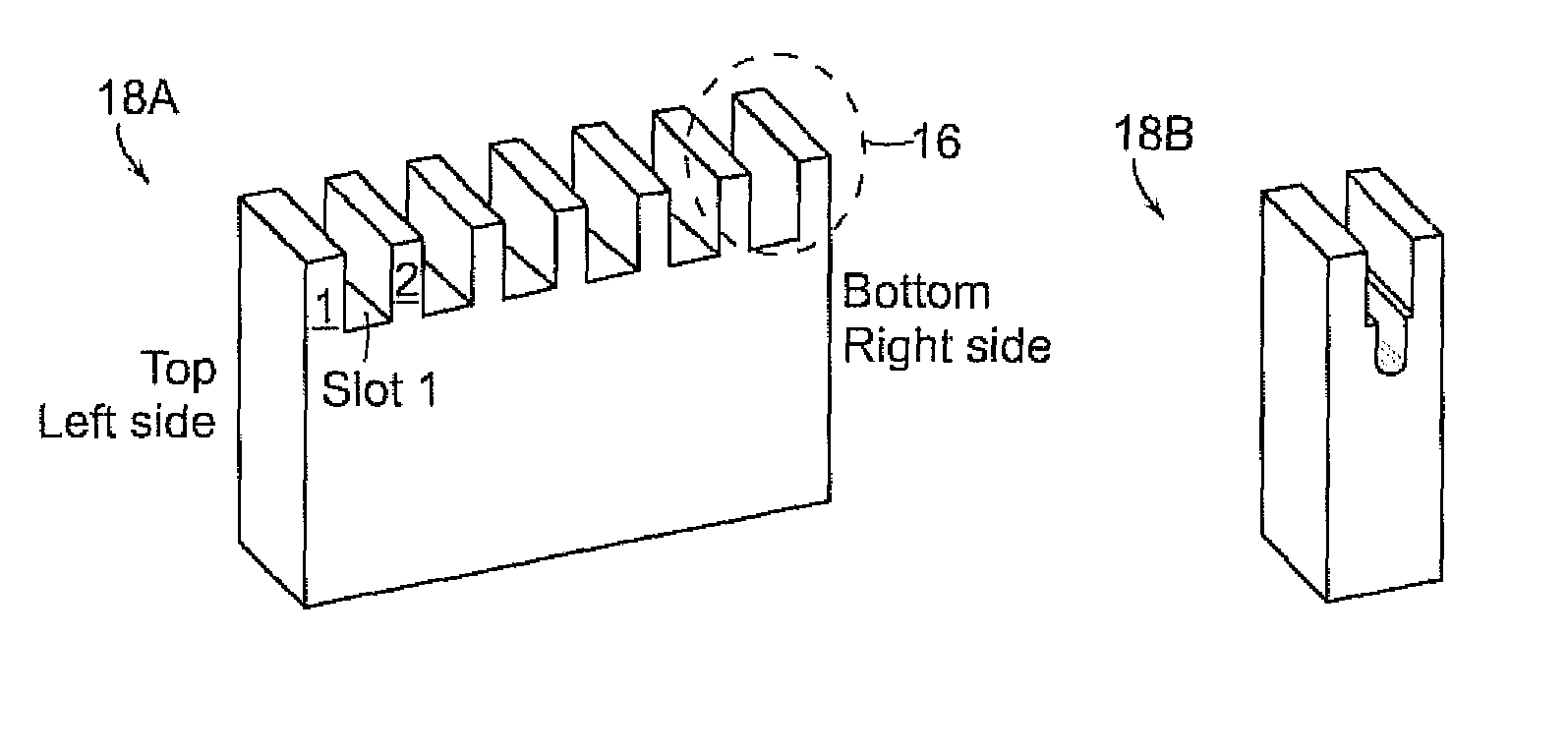
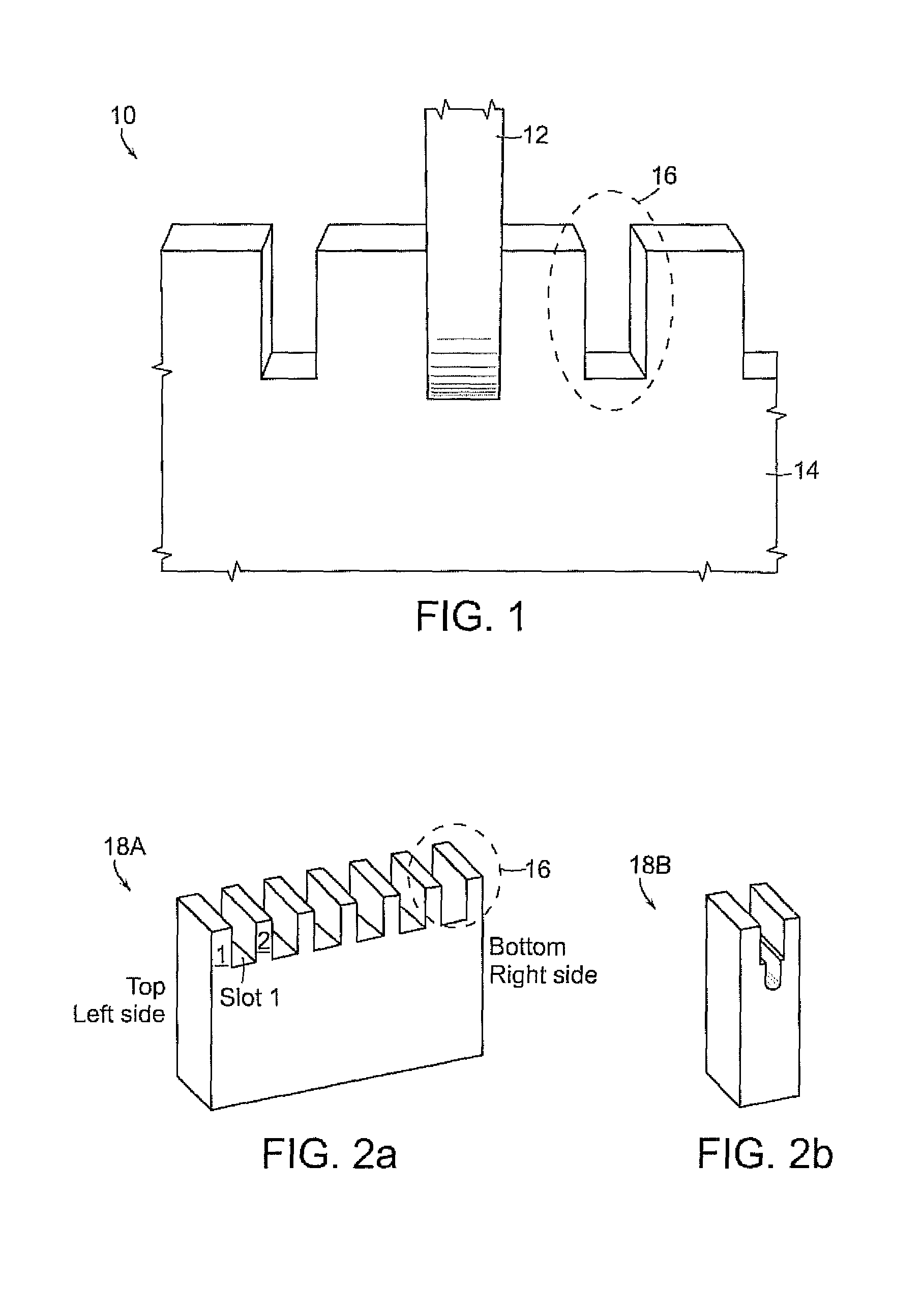
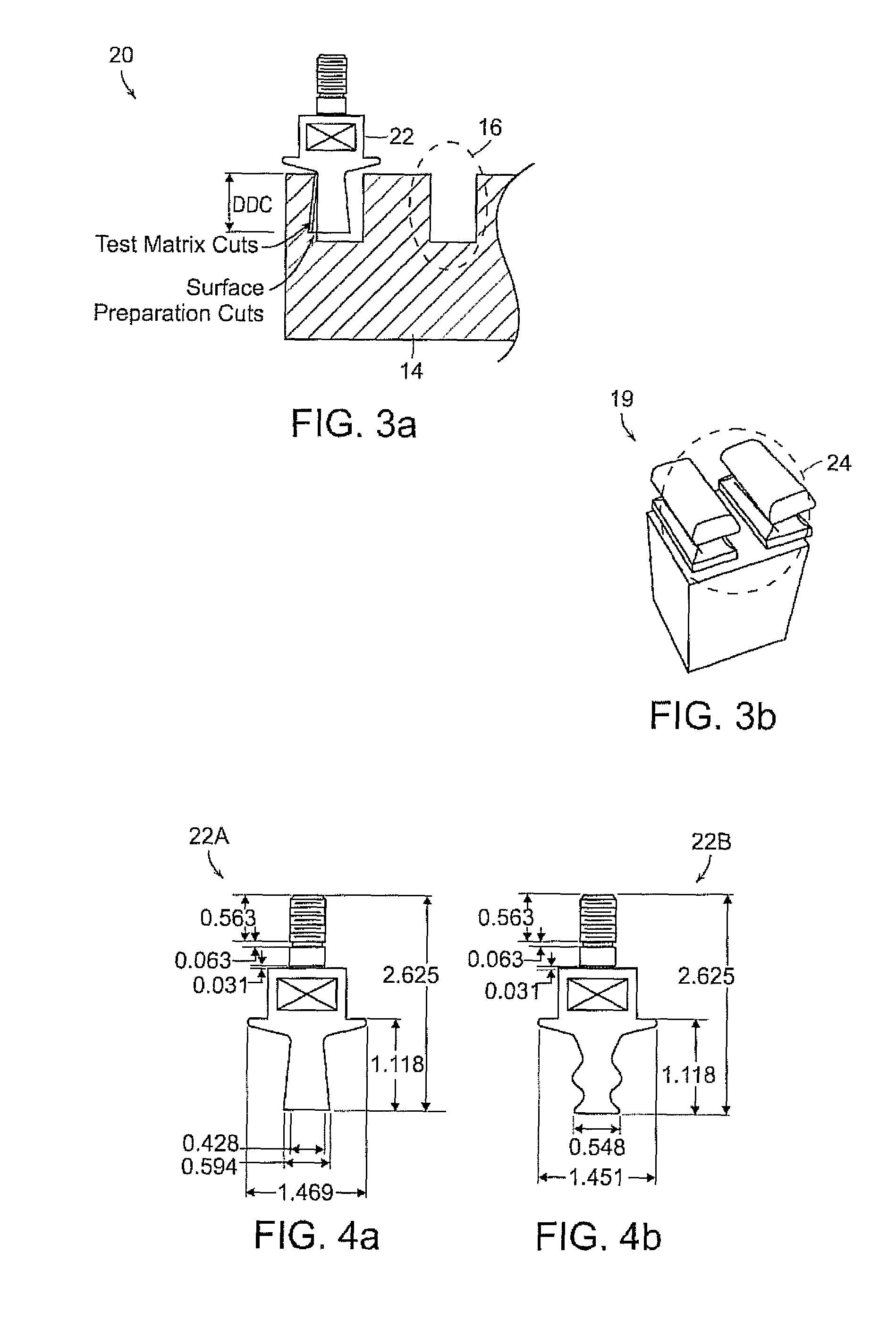
[0015]As used herein, the term “complex shape” means a shape or a part that has an angle that is re-entering or pointing inward and which does not allow a mating form to be removed in a direction normal to one of three axes (i.e., x, y or z). An example of the complex shape includes a re-entrant shape. As used herein, the “re-entrant shape” means a shape or a part that has an angle that is re-entering or pointing inward, and is wider at the inside than it is at the entrance. An example of the re-entrant shape is a dovetail slot.

[0016]The slot formation processes of the invention remove the bulk of material, minimizing the amount of ma...


PUM

PropertyMeasurementUnit
sizeaaaaaaaaaa
speedaaaaaaaaaa
speedaaaaaaaaaa

Abstract

A method of producing a complex shape in a workpiece includes the steps of: i) grinding a workpiece at a maximum specific cutting energy of about 10 Hp / in3·min with at least one bonded abrasive tool, thereby forming a slot in the workpiece; and ii) grinding the slot with at least one mounted point tool, thereby producing the complex shape in the slot. The bonded abrasive tool includes at least about 3 volume % of a filamentary sol-gel alpha-alumina abrasive grain having an average length-to-cross-sectional-width ratio of greater than about 4:1 or an agglomerate thereof. A method of producing a slot in a metallic workpiece having a maximum hardness value of equal to, or less than, about 65 Rc includes the step of grinding the workpiece with a bonded abrasive tool at a material removal rate in a range of between about 0.25 in3 / min·in and about 60 in3 / min·in and at a maximum specific cutting energy of about 10 Hp / in3·min.

Description

BACKGROUND OF THE INVENTION[0001]A re-entrant shape is a form which is wider at the inside than it is at the entrance (e.g., a dovetail joint). Turbine components, such as jet engine, rotors, compressor blade assembly, typically employ re-entrant shaped slots in the turbine disks. The re-entrant shape is used to hold or retain turbine blades around the periphery of turbine disks. Mechanical slides, T-slots to clamp parts on a machine table also use such re-entrant shaped slots.[0002]This type of form cannot generally be created by grinding with a large diameter wheel operated perpendicular to the surface of the part because it would be impossible for the wheel to enter the wider part of the form without removing the narrower part of the form. Typically, broaching or milling has been used in the aerospace industry to produce such a complex shape. Broaching a re-entrant shape, however, is costly partly due to high tooling costs, such as expensive machinery, set-up costs, tooling regri...

Claims


Application Information

Patent Timeline
Patent Type & Authority Patents(United States)
IPC IPC(8): B24B1/00
CPCB24B1/00B24D3/18B24B19/02
Inventor SUBRAMANIAN, KRISHNAMOORTHYWEBSTER, JOHN A.CAPUTA, IV, PETER
Owner SAINT GOBAIN ABRASIVES INC
Learn More