
Electrochemical system with fluid passage integrated within a sealing bead

a technology of electrochemical system and fluid passage, which is applied in the direction of electrochemical generator, electrochemical components, electric apparatus, etc., can solve the problems of hsub>2 /sub>occurring, affecting the operation of electrochemical cells, and increasing the cost of mechanical compression of hydrogen

Active Publication Date: 2010-05-18
REINZ DICHTUNGS
View PDF20 Cites 38 Cited by
  • Summary
  • Abstract
  • Description
  • Claims
  • Application Information

AI Technical Summary

Benefits of technology

[0018]A further advantageous embodiment envisages that the bead arrangement is made from steel. Steel has the advantage that it can be processed very cost-effectively using conventional tools, in addition, for example methods for coating steel with thin elastomer layers are well tested. The good elasticity properties of steel facilitate the good design of the long resilient sealing region of the invention according to the invention. There is thus the particular possibility that the bead arrangement is attached to the bipolar plate. There is thus firstly the possibility that the bipolar plate is designed as a whole as a steel moulding (which is possibly provided with a coating for corrosion resistance or conductivity in some regions). However, it is also possible that the bipolar plate is designed as a composite element of two steel plates with a plastic plate lying therebetween. However, in each case the good manufacturing possibilities of steel may be utilised, it is possible to make the bead arrangement within a manufacturing step which is taking place in any case (for example embossing of a flow field, that is a “stream field”). Very low costs are thus produced, also no additional sources of error are provided by extra components, such as for example additionally inserted elastomer seals.
[0040]A further advantageous development envisages that an electrochemically active region of the electrochemical cell is arranged in an essentially closed chamber, which is limited essentially annularly laterally by a bead arrangement. This means that a bead arrangement is possible not only for sealing openings of the bipolar plate, but that also “total sealing” of the interior of the electrochemical cell stack is possible.

Problems solved by technology

This electrochemical compression is available particularly for small quantities of hydrogen to be compressed, since mechanical compression of hydrogen would be considerably more expensive here.
Difficulties regularly result here particularly with regard to the gas diffusion layer.
It is now a problem for the inserted gas diffusion layer that it may be designed as a fibre mat (with metal fibres) or metal mesh.
In addition, it is also not recommended to compensate production tolerances of the fibre mat by compressing the mat, since the gas permeability of the mat layer is thus severely diminished and hence operation of the electrochemical cell is restricted.
In addition, particularly for electrochemical cells operated using molecular hydrogen, permeation losses of H2 occur which diffuse through the elastomer seal.
Since the electrochemical compressor stack is stabilised externally by end plates which are held together using tension bands or the like, yielding of the stacked individual plates is only possible to a limited extent.
This ensures that the degree of deformation is limited in the bead region, so that there cannot be complete flat pressing of the bead.
If the seal of a metallic bipolar plate is designed as a bead construction, the bead is in most cases severely flattened at the points through which media should flow into the active region.
Support for the membrane is not present at these points, which may lead to gas leakages (“cross-over”) or to the collapse of the membrane into the supply channel.

Method used


Image

  • Electrochemical system with fluid passage integrated within a sealing bead
  • Electrochemical system with fluid passage integrated within a sealing bead
  • Electrochemical system with fluid passage integrated within a sealing bead

Examples


Embodiment Construction

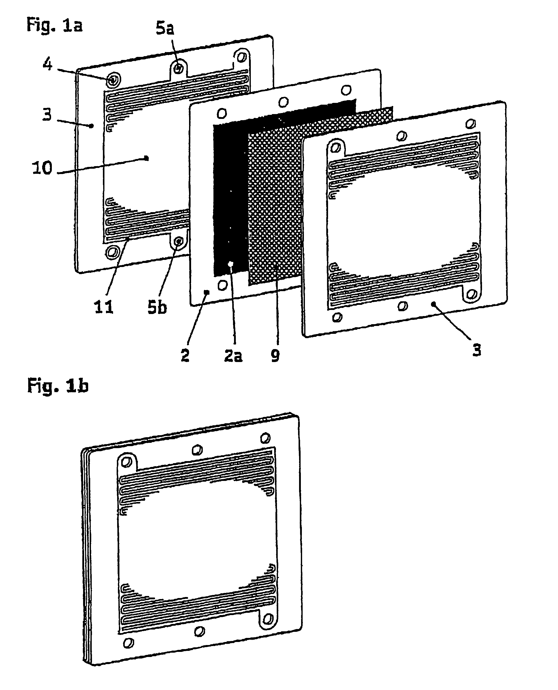
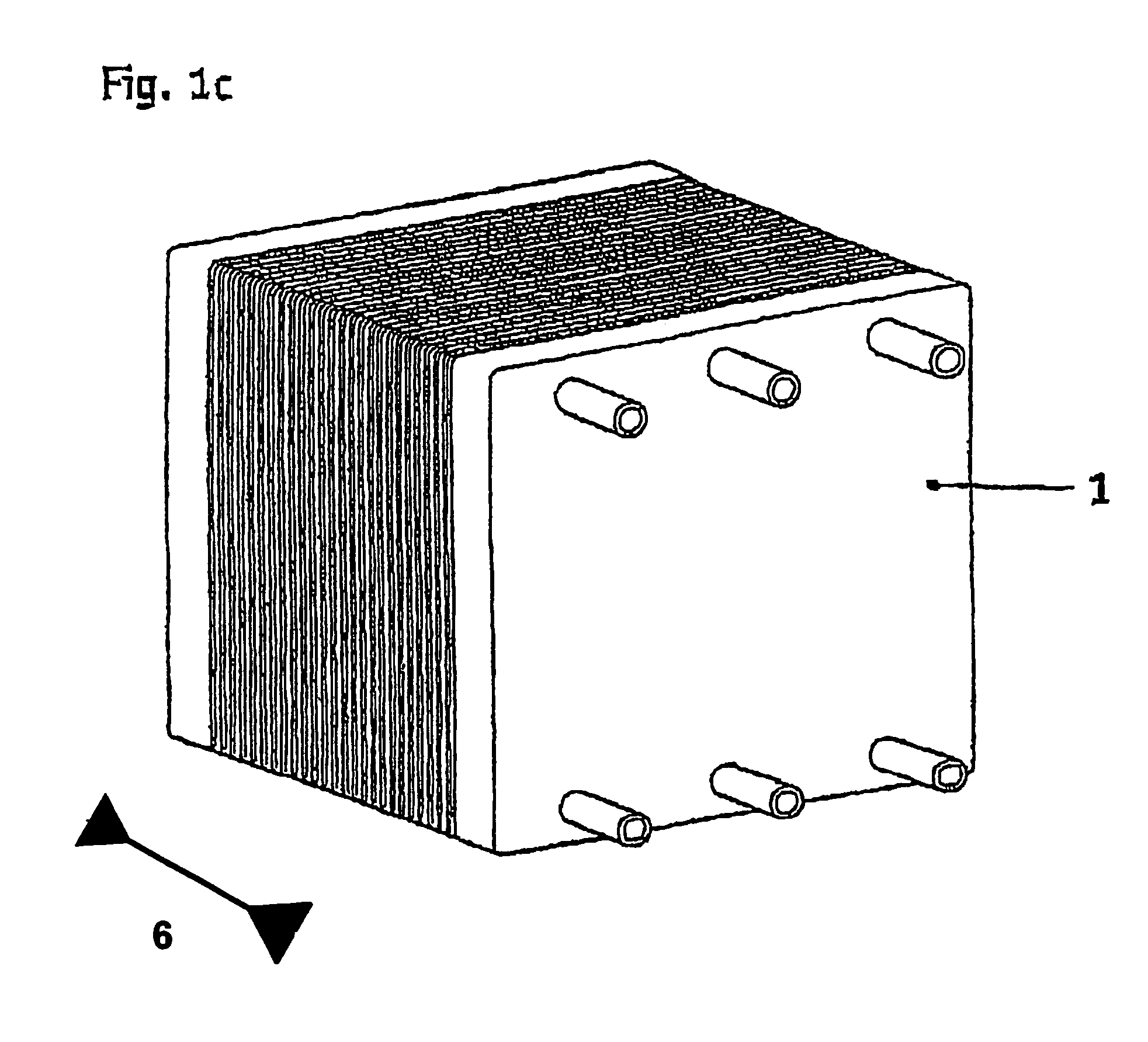
[0051]FIG. 1a shows the construction of an electrochemical cell, as shown in FIG. 1b. A plurality of electrochemical cells form in layers the region of an electrochemical cell stack 1 arranged between end plates (see FIG. 1c).

[0052]An electrochemical cell 2 with its usual components can be seen in FIG. 1a and has for example an ion-conducting polymer membrane, which is provided in the central region 2a with a catalyst layer on both sides. Two bipolar plates 3, between which the polymer membrane is arranged, are provided in the electrochemical cell. A gas diffusion layer 9, which has dimensions so that it can be accommodated in a recess of the bipolar plate, is also arranged in the region between each bipolar plate and the polymer membrane (optionally, depending on the fine structuring of the bipolar plate). In the assembled state of the electrochemical cell (FIG. 1b), the electrochemically active region of the electrochemical cells, which is covered essentially by the gas diffusion ...


PUM

PropertyMeasurementUnit
Mechanical propertiesaaaaaaaaaa
Resilienceaaaaaaaaaa

Abstract

The invention deals with an electrochemical system for compressing gases and / or for producing gases by electrolysis, consisting of an electrochemical compressor stack (1) having layering of several electrochemical cells, which are separated from one another in each case by bipolar plates (3; 3′), wherein the bipolar plates have openings for media supply and media discharge (5a, 5b) for the electrochemical cells and the electrochemical cell stack can be placed under mechanical compressive strain in direction (6) of the layering. The bead arrangements (7; 7′) are resilient and are provided at least in some regions to seal the openings (4, 5a, 5b) and / or an electrochemically active region (10) of the electrochemical cells.

Description

FIELD OF THE INVENTION[0001]The present invention relates to an electrochemical system, such as for example a fuel cell system or an electrochemical compressor system.BACKGROUND OF THE INVENTION[0002]Electrochemical compressor systems may be, for example electrolysers, which by applying a potential, in addition to producing, for example water and oxygen from water, compress these gases at the same time under high pressure.[0003]In addition, electrochemical compressor systems, such as for example electrochemical hydrogen compressors, are also known, to which gaseous molecular hydrogen is supplied and the latter is compressed electrochemically by applying a potential. This electrochemical compression is available particularly for small quantities of hydrogen to be compressed, since mechanical compression of hydrogen would be considerably more expensive here.[0004]Electrochemical systems are known, in which an electrochemical cell stack is constructed with layering of several electroch...

Claims


Application Information

Patent Timeline
IPC IPC(8): H01M2/00C25B9/20H01M8/02H01M8/10H01M8/24
CPCC25B9/203H01M8/0228H01M8/0232H01M8/0247H01M8/0254H01M8/0267H01M8/0271H01M8/1002H01M8/247H01M8/0206Y10T29/49002H01M8/021H01M8/0213H01M8/0221H01M8/0256H01M8/0263Y02E60/366Y02E60/521H01M8/1007Y02E60/50C25B9/75C25B11/036H01M8/2483H01M8/241H01M8/2457Y02E60/36
Inventor STROBEL, RAIMUNDGAUGLER, BERNDSAILER, ALBRECHTKUNZ, CLAUDIASCHERER, JOACHIMSCHLEIER, CHRISTIANWALDVOGEL, JOHANN
Owner REINZ DICHTUNGS
Learn More