Vehicular generator-motor control apparatus

a technology of motor control and generator, which is applied in the direction of electric generator control, electric commutator, engine starter, etc., can solve the problems of discontinuous torque, unfavorable control of motor speed, so as to enhance the torque

Active Publication Date: 2010-05-25
MITSUBISHI ELECTRIC CORP
View PDF34 Cites 11 Cited by
  • Summary
  • Abstract
  • Description
  • Claims
  • Application Information

AI Technical Summary

Benefits of technology

[0011]A vehicular generator-motor control apparatus according to this invention is a vehicular generator-motor control apparatus wherein a winding field type salient-pole generator-motor for a vehicle is subjected to a conduction control by a DC-AC converter. In the control apparatus, a stator of the vehicular winding field type salient-pole generator-motor is energized by rectangular wave voltages at those conduction start angles of respective phases of the stator which are shifted a predetermined angle relative to a rotor position. Besides, the conduction start angles of the respective phases change substantially continuously in accordance with an input voltage of the -DC-AC converter and a revolution speed of the generator-motor. Thus, the control apparatus brings forth the advantage of enhancing a torque.

Problems solved by technology

Therefore, the torque becomes discontinuous, and the revolution speed does not become smooth.
On account of the discontinuous current, electromagnetic noise suddenly enlarges at the changeover of the two modes, so that an uneasy feeling is incurred.
Therefore, the capability of the motor cannot be exploited to the utmost.
Especially a battery for the automobile usually has a voltage of 12 V, and the lowering of the torque is drastic when the voltage utilization factor is low.
In a case where a rotor has non-salient poles, a reluctance torque is not generated even by changing the phases of stator currents, and the phase changes are less effective.

Method used


Image

  • Vehicular generator-motor control apparatus
  • Vehicular generator-motor control apparatus
  • Vehicular generator-motor control apparatus

Examples


embodiment 1

[0029]Now, Embodiment 1 of this invention will be described with reference to FIGS. 1-8. Incidentally, throughout the drawings, identical numerals and signs indicate identical portions.

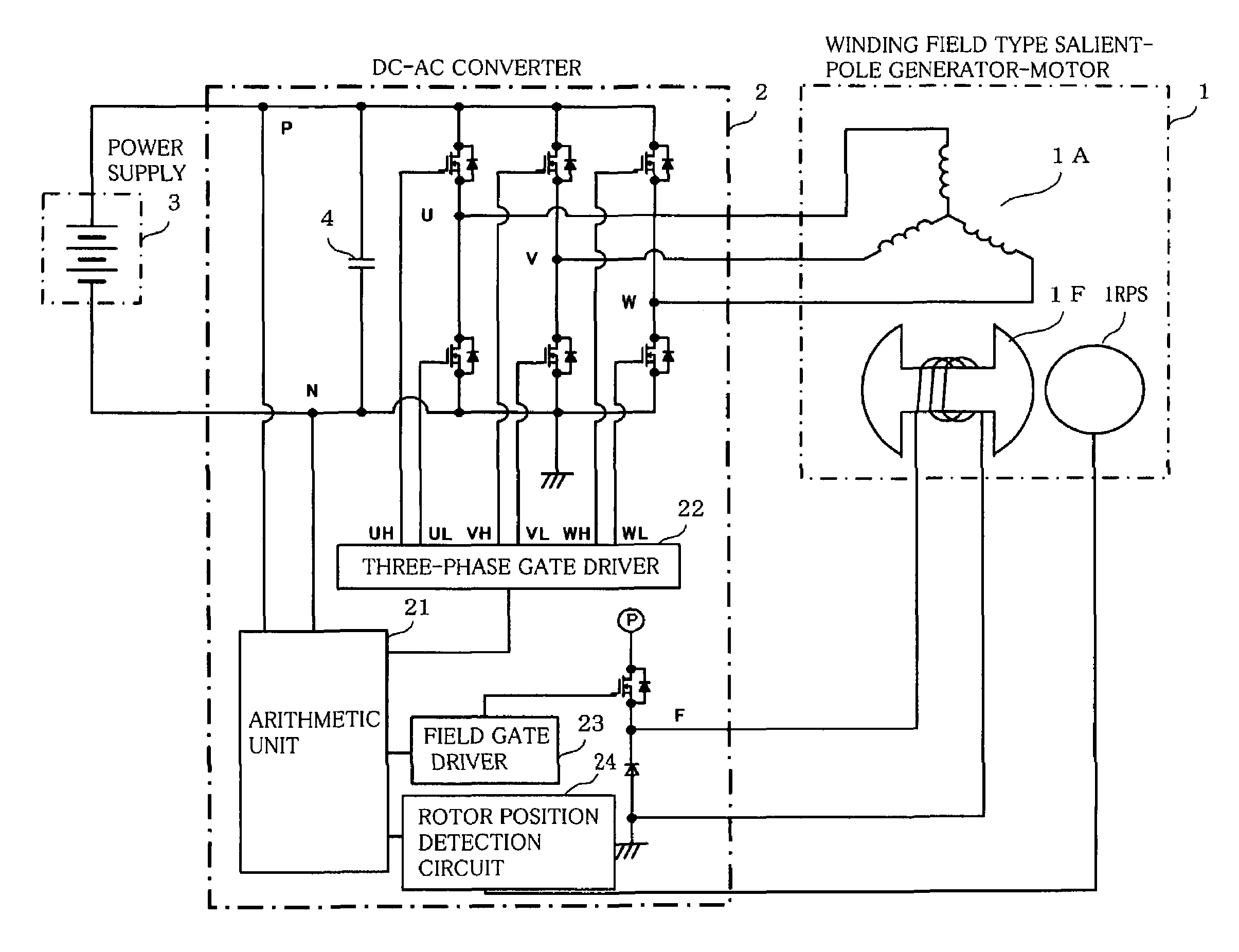
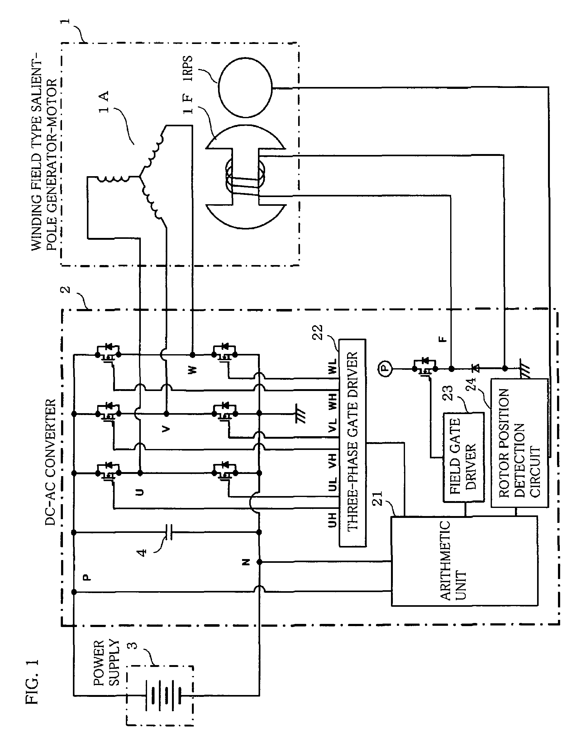
[0030]FIG. 1 shows a circuit diagram of a winding field type salient-pole generator-motor 1, a DC-AC converter 2 which inputs and outputs currents to and from the generator-motor 1, a DC power supply 3 such as battery, and a smoothing capacitor 4.

[0031]The winding field type salient-pole generator-motor 1 includes a stator (usually, armature) 1A having a winding of Y-connection, a rotor (usually, field magnet) 1F having a winding, and a rotor position sensor 1RPS.

[0032]The DC-AC converter 2 includes an arithmetic unit 21, a three-phase gate driver 22, a field gate driver 23, and a rotor position detection circuit 24.

[0033]The arithmetic unit 21 computes a conduction start angle of each phase of the stator 1A by using a P-N voltage which is the input voltage of the DC-AC converter 2, and that revolutio...

embodiment 2

[0041]Now, Embodiment 2 of this invention will be described with reference to FIG. 9. FIG. 9 shows the set value change of the U-phase conduction start angle dependent upon the temperature of the stator coil of the generator-motor. Thus, the torque can be controlled to the maximum torque or the target torque at each temperature. The temperature of the stator coil may well be substituted by the temperature of the DC-AC converter. Besides, on the occasion of the first engine start at a low temperature, all of the generator-motor, the DC-AC converter and an engine are at substantially equal temperatures, and hence, the conduction start angle may well be set in accordance with the water temperature or oil temperature of the engine.

embodiment 3

[0042]Now, Embodiment 3 of this invention will be described with reference to FIG. 10. In FIG. 10, portions identical or equivalent to those in FIG. 1 are assigned the same numerals and signs as in FIG. 1. FIG. 10 shows a circuit which uses a shunt resistance 6 as field current detection means. The resistance Rt1 of the rotor field winding of a generator-motor changes depending upon temperatures, as indicated by the following formula (Formula 1):

Rt1=(235+t1) / (235+t0)·Rt0  (Formula 1)

where

[0043]t1: actual service temperature,

[0044]t0: reference temperature at which Rt0 has been measured,

[0045]Rt0: resistance at the reference temperature.

Besides, a field current If is determined by the voltage VPN of a power supply, the ON duty (“Duty ”) of a field switching element 5, and the voltage drop of the resistance Rt1 of the field winding, etc., as follows:

If=(VPN·Duty−Vdrop) / Rt0  (Formula 2)

where

[0046]Vdrop: voltage drop of a brush.

[0047]The temperature as in the second embodiment affects t...


PUM


Abstract

A vehicular generator-motor control apparatus wherein a winding field type salient-pole generator-motor 1 (in FIG. 1) for a vehicle is subjected to a conduction control by a DC-AC converter 2, characterized in that a stator 1A of the vehicular winding field type salient-pole generator-motor 1 is energized by rectangular wave voltages at those conduction start angles δ of respective phases of the stator 1A which are shifted a predetermined angle relative to a rotor position, and that the conduction start angles δ of the respective phases change substantially continuously in accordance with an input voltage of the DC-AC converter 2 and a revolution speed of the generator-motor 2.

Description

BACKGROUND OF THE INVENTION[0001]1. Field of the Invention[0002]This invention relates to a vehicular generator-motor control apparatus wherein currents are inputted to and outputted from a vehicular generator-motor by a DC-AC converter.[0003]2. Description of the Related Art[0004]JP-T-2004-519184 (FIGS. 2 and 3, and the explanations thereof), for example, adopts a method for controlling a reversible multiphase rotary electric equipment. The method is characterized in that, in actuating as a motor a generator-motor which serves as both a generator and the motor, the electric equipment is driven in accordance with two modes which correspond to different speed / torque characteristic curves, that is, a first mode which is called “starter mode ” and in which the thermal engine of an automobile can be driven so as to start the automobile at a low speed and with a large torque, and a second mode which is called “auxiliary motor mode ” and in which only the electric equipment, at least one ...

Claims


Application Information

Patent Timeline
Patent Type & Authority Patents(United States)
IPC IPC(8): H02P7/32H02P6/06H02P6/16H02P6/32
CPCF02N11/04H02P9/24H02P6/14F02N2011/0874H02P2101/45
Inventor FUJITA, MASAHIKOASAO, YOSHIHITO
Owner MITSUBISHI ELECTRIC CORP
Why Eureka
Try Eureka