Weep venting system for masonry walls

a technology for venting systems and masonry walls, applied in the direction of walls, construction, building components, etc., can solve the problems of not being able to easily pull out masonry walls, and moving forward, and achieve the effect of efficient cutting

Active Publication Date: 2010-06-08
KEENE BUILDING PRODS
View PDF34 Cites 15 Cited by
  • Summary
  • Abstract
  • Description
  • Claims
  • Application Information

AI Technical Summary

Benefits of technology

[0003]The present invention provides a unique weep vent which is easily fabricated, is lightweight, and has relative structural rigidity while permitting free drainage of moisture therethrough and while substantially blocking entry or reverse flow of unwanted particulate materials. To this end, weep vent members are provided for insertion at selected, spaced locations in a masonry wall of a building structure between adjacent masonry elements such as bricks, blocks, stone, faux stone and the like.
[0005]One preferred form features a trapezoidal shape that can be cut efficiently from a sheet or strip of material having a substantially uniform thickness that substantially equals that of the mortar joints areas into which the weep vent members are to be inserted between adjacent elements of masonry walls. The tapered character of the weep vent members not only provides for efficient manufacture but also provides a configuration that resists forward movement of the installed weep vent members; thus, the members are not easily pulled out of masonry walls by vandals, nor do they move forwardly over time so as to project unattractively from the walls in which they have been installed during wall construction. The filaments or strands are preferably polymeric and capable of being heat bonded at their random intersections when the weep vent members are fabricated. Weep vent members, formed as described herein, may be readily positioned in association with a course or courses of brick, block, stone, faux stone or the like without detracting from the structural integrity of the wall.

Problems solved by technology

The tapered character of the weep vent members not only provides for efficient manufacture but also provides a configuration that resists forward movement of the installed weep vent members; thus, the members are not easily pulled out of masonry walls by vandals, nor do they move forwardly over time so as to project unattractively from the walls in which they have been installed during wall construction.

Method used


Image

  • Weep venting system for masonry walls
  • Weep venting system for masonry walls
  • Weep venting system for masonry walls

Examples


Embodiment Construction

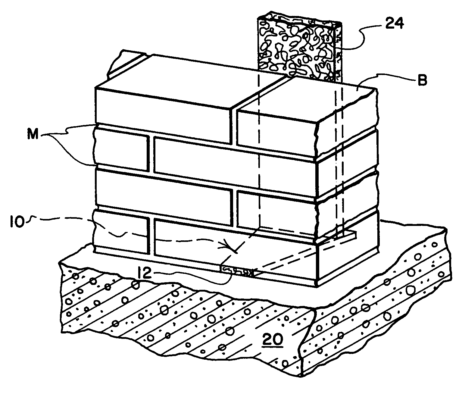
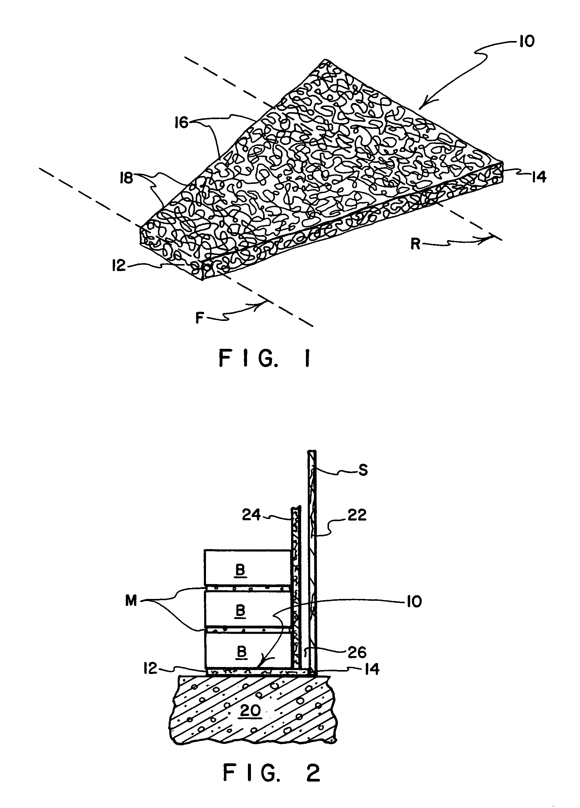
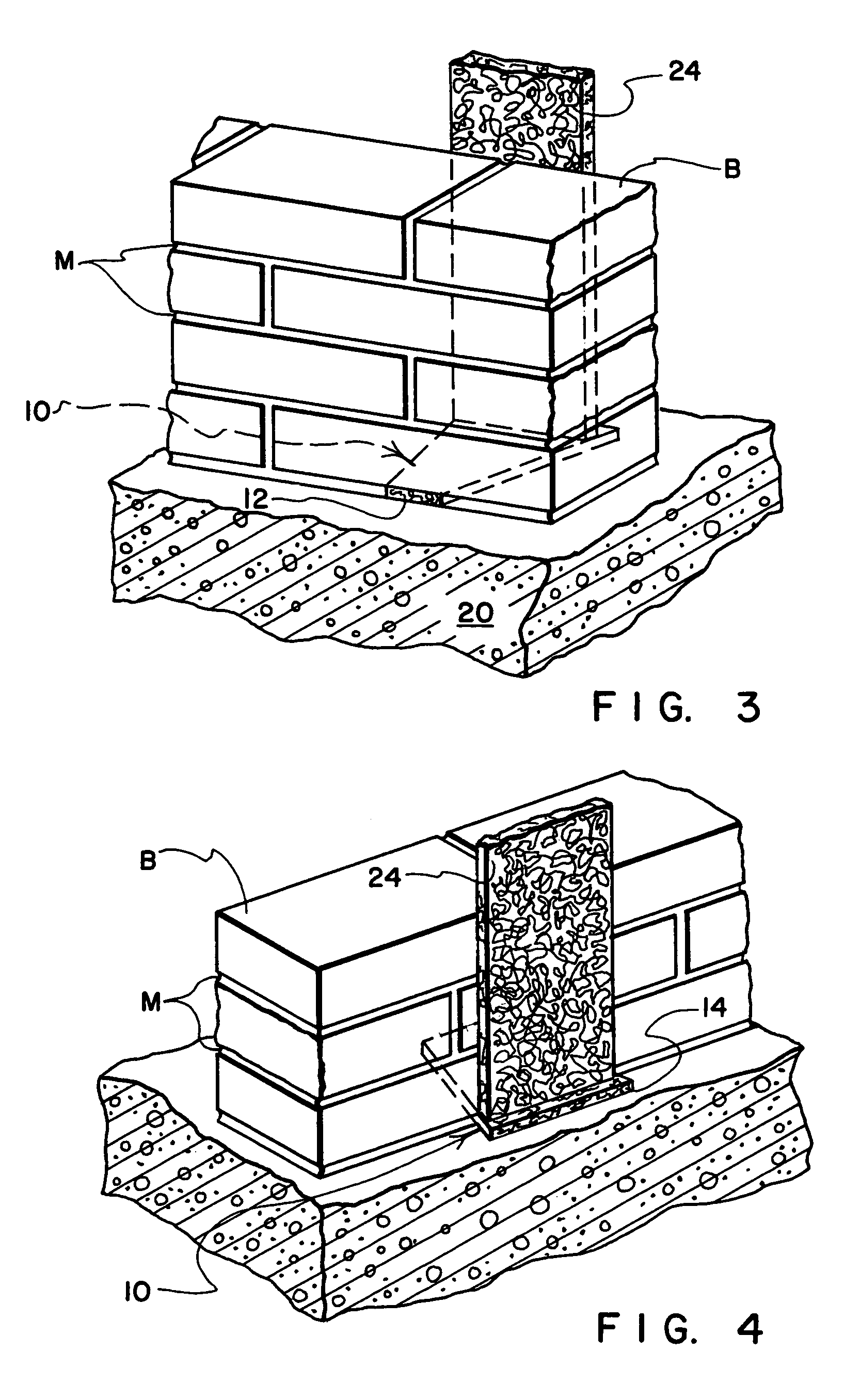
[0011]Referring to the drawings, there is shown in FIG. 1 at 10 the subject weep vent in a preferred form for utilization. In the form shown, the weep vent 10 is generally trapezoidal or as a truncated triangle as shown in phantom lines. The weep vent 10 has a narrower forward end region 12, and a wider rearward end region 14. While a trapezoidal shape is preferred due to the efficiency with which weep vent members of this type can be cut from a sheet of bonded filament material, a feature that resides at the heart of the invention is the provision of a weep vent member that has a wider inner, rear or interior end region and a relatively narrower outer, front or exterior end region, and that therefore narrows in cross-section as the member extends from its inner, rear or interior end region toward its outer, front or exterior end region.

[0012]The weep vent 10 is formed from an intertangled mass of filaments, strands or strips 16. The many filaments, strands or strips that form the o...


PUM


Abstract

A system for venting moisture from wall and building structures, especially masonry walls constructed from masonry elements such as of brick, block, stone, faux stone or the like, without weakening the wall or building structure, utilizes open matrix weep vent members that are fabricated, for example from a mass of intertwined and intertangled polymeric filaments that are bonded at a plurality of intersections thereby to form one-piece or unit-handled weep vent members that preferably are inserted in place of mortar at spaced locations along horizontally extending mortar joints between rows of bricks, blocks or other masonry wall elements. Weep vent members that embody the present invention have wider portions at their rearward or intake end regions, and narrower portions at their forward or discharge end regions, with a preferred form characterized by a generally trapezoidal shape that helps to retain the weep vent members in their associated mortar joints, and that provide a funnel-like ducting of moisture from their relatively wider rear end regions toward their relatively narrower forward end regions.

Description

BACKGROUND OF THE INVENTION[0001]In exterior walls of masonry structures, as houses or commercial buildings, there are a number of locations in the design of the building structure wherein ambient moisture-laden air may become relatively trapped in still air, and in time condense in droplets or drops on adjacent surfaces of masonry, wood or metal which may not be visible to an observer or exposed for treatment. There has been substantial development of devices and arrangements for leading moisture away from relatively trapped areas in masonry and other types of building construction in an effort to overcome this problem. It is well known, for example, to provide drainage tubes through brick walls, to provide porous plugs adjacent the brick that are intended to dissolve in contact with water so that the water may drain, and to insert rigid tubular members in mortar joint areas between adjacent brick.[0002]A proposal also has been made to utilize rectangular blocks of randomly oriente...

Claims


Application Information

Patent Timeline
Patent Type & Authority Patents(United States)
IPC IPC(8): E04B2/28E04B1/70E04F17/00
CPCE04B1/7061
Inventor KEENE, JAMES R.
Owner KEENE BUILDING PRODS
Why Eureka
Try Eureka