
High threshold NMOS source-drain formation with As, P and C to reduce damage

a technology of source-drain and high-threshold nmos, which is applied in the field of integrated circuits, can solve the problems of high diffusivity of p atoms, disadvantages of phosphorus use in nldd and nsd, and disadvantages of phosphorus use in nsd and nsd

Active Publication Date: 2010-06-15
TEXAS INSTR INC
View PDF5 Cites 10 Cited by
  • Summary
  • Abstract
  • Description
  • Claims
  • Application Information

AI Technical Summary

Benefits of technology

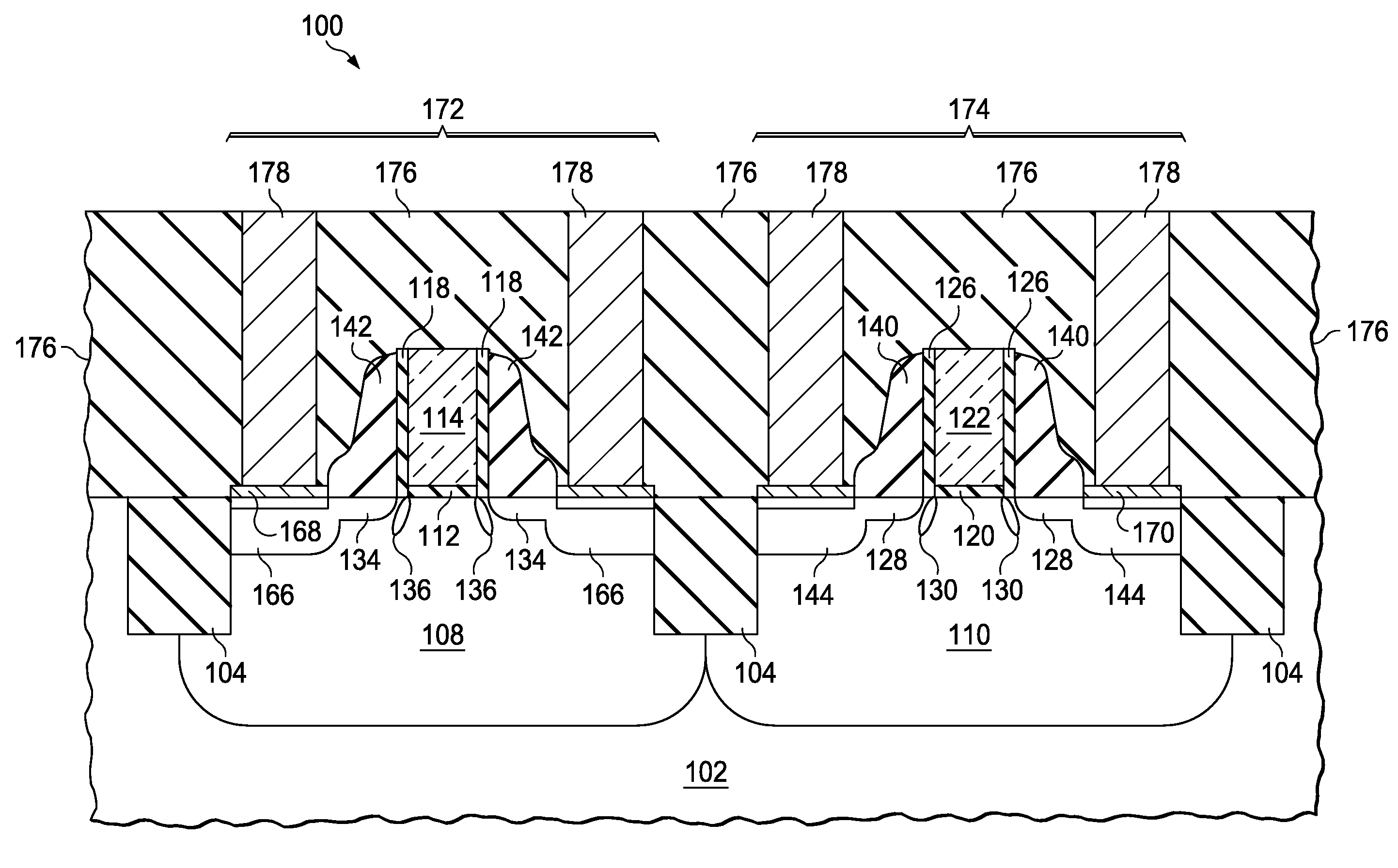
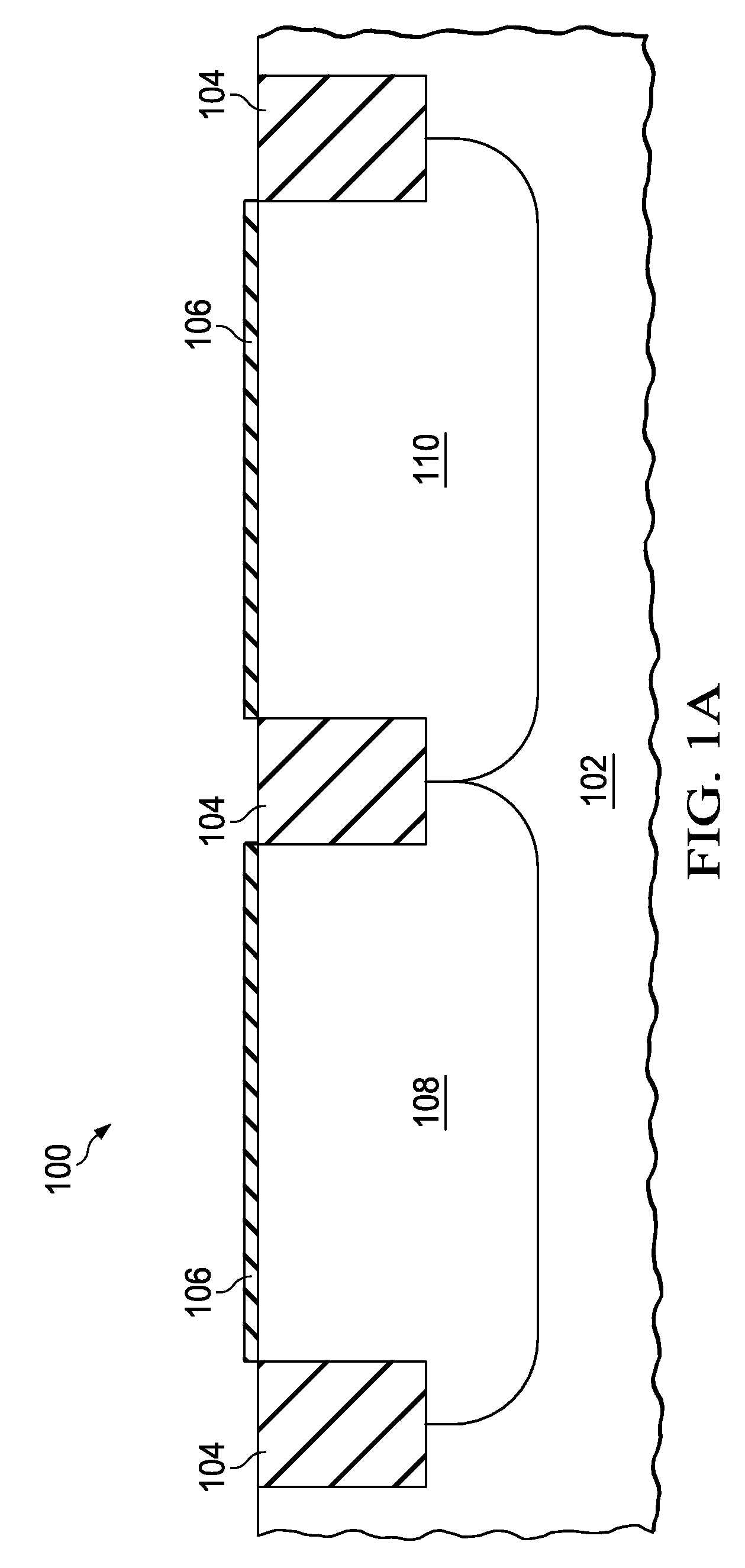
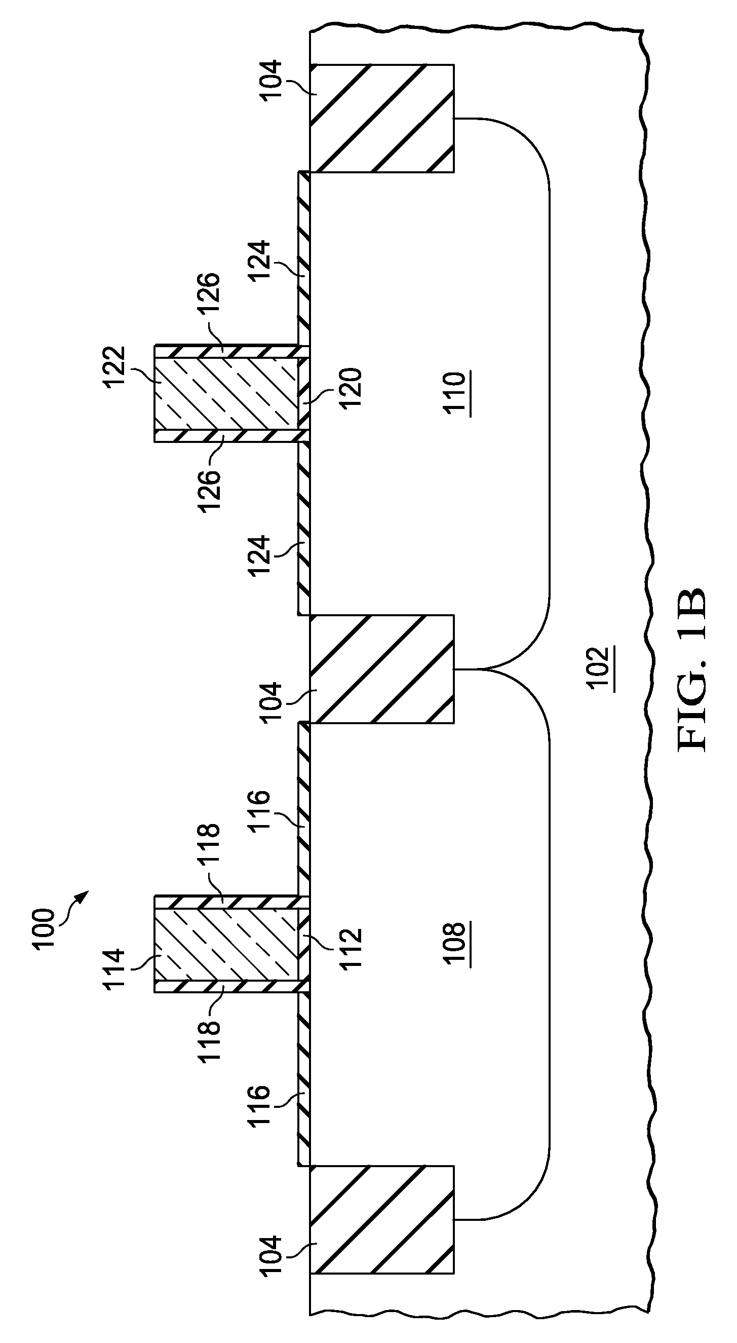
The invention provides a method for forming NMOS transistors with reduced off-state leakage current, reduced GDL, and reduced occurrence of pipe defects. This is achieved by not implanting carbon into the NLDD and using a pre-amorphizing implant, a phosphorus implant, and a carbon species implant to form the NSD. In an alternate embodiment, a high threshold NMOS transistor may be formed according to the inventive method. The NSD may contain less than 1·1014 cm−2 arsenic. The method and an integrated circuit incorporating the inventive method are also disclosed.

Problems solved by technology

Phosphorus has a disadvantage for use in the NLDD and NSD, which arises from the high diffusivity of P atoms in silicon.
A common p-type dopant for halo implants is boron (B), which has the same disadvantage of high diffusivity as phosphorus.
However, carbon atoms in the NLDD space charge region contribute to diode leakage current, known as gated diode leakage (GDL).
However, arsenic has a disadvantage of causing damage to the silicon crystal lattice during ion implantation, which is correlated with formation of metal silicide defects, known as pipes, which cause undesirable high off-state leakage current, and failures in static random access memory (SRAM) bits.
GDL from the reverse biased junction between the drain and the p-type channel region is a dominant source of off-state leakage current in high threshold NMOS transistors, which is undesirable for IC performance.

Method used


Image

  • High threshold NMOS source-drain formation with As, P and C to reduce damage
  • High threshold NMOS source-drain formation with As, P and C to reduce damage
  • High threshold NMOS source-drain formation with As, P and C to reduce damage

Examples


Embodiment Construction

[0010]The present invention is described with reference to the attached figures, wherein like reference numerals are used throughout the figures to designate similar or equivalent elements. The figures are not drawn to scale and they are provided merely to illustrate the invention. Several aspects of the invention are described below with reference to example applications for illustration. It should be understood that numerous specific details, relationships, and methods are set forth to provide a full understanding of the invention. One skilled in the relevant art, however, will readily recognize that the invention can be practiced without one or more of the specific details or with other methods. In other instances, well-known structures or operations are not shown in detail to avoid obscuring the invention. The present invention is not limited by the illustrated ordering of acts or events, as some acts may occur in different orders and / or concurrently with other acts or events. F...


PUM


Abstract

Pipe defects in n-type lightly doped drain (NLDD) regions and n-type source / drain (NDS) regions are associated with arsenic implants, while excess diffusion in NLDD and NSD regions is mainly due to phosphorus interstitial movement. Carbon implantation is commonly used to reduce phosphorus diffusion in the NLDD, but contributes to gated diode leakage (GDL). In high threshold NMOS transistors GDL is commonly a dominant off-state leakage mechanism. This invention provides a method of forming an NMOS transistor in which no carbon is implanted into the NLDD, and the NSD is formed by a pre-amorphizing implant (PAI), a phosphorus implant and a carbon species implant. Use of carbon in the NDS allows a higher concentration of phosphorus, resulting in reduced series resistance and reduced pipe defects. An NMOS transistor with less than 1·1014 cm−2 arsenic in the NSD and a high threshold NMOS transistor formed with the inventive method are also disclosed.

Description

FIELD OF THE INVENTION[0001]This invention relates to the field of integrated circuits. More particularly, this invention relates to formation of source and drain elements of n-channel MOS transistors in integrated circuits.BACKGROUND OF THE INVENTION[0002]It is well known that dimensions of transistors in integrated circuits (ICs) are shrinking with each new generation of fabrication technology, as articulated in Moore's Law. Source and drain elements of MOS transistors are shrinking in both lateral and vertical directions, requiring tighter control over dopant distributions to maintain transistor performance parameters such as on-state drive current and off-state leakage current. Source and drain elements of n-channel MOS transistors typically include two sub-elements: a shallow, lightly doped region, commonly known as the n-type lightly doped drain (NLDD) closest to the MOS transistor channel region, and a deeper, heavily doped region commonly known as the n-type source / drain (NS...

Claims


Application Information

Patent Timeline
Patent Type & Authority Patents(United States)
IPC IPC(8): H01L21/336
CPCH01L21/26506H01L21/26586H01L21/823412H01L29/7833H01L29/0847H01L29/6659H01L21/823418H01L21/26513
Inventor KOHLI, PUNEETMEHROTRA, MANOJTANG, SHAOPING
Owner TEXAS INSTR INC
Learn More