
Semiconductor device

a semiconductor and device technology, applied in semiconductor devices, magnetotherapy using permanent magnets, medical science, etc., can solve the problems of difficult to achieve a desired withstand voltage characteristic, difficult to reduce an on-resistance value, and excessive storage of minority carriers (holes) of free carriers. , to achieve the effect of preventing the deterioration of the withstand voltage characteristic, preventing and suppressing the expansion of the depletion layer

Active Publication Date: 2010-06-15
SEMICON COMPONENTS IND LLC
View PDF27 Cites 9 Cited by
  • Summary
  • Abstract
  • Description
  • Claims
  • Application Information

AI Technical Summary

Benefits of technology

This configuration allows for lower ON-resistance, improved withstand voltage characteristics, and reduced reverse recovery current rates, effectively protecting circuit elements from overvoltage and maintaining performance in high-frequency applications.

Problems solved by technology

This causes a problem in which a parasitic resistance is high in the epitaxial layer, thereby making it impossible to reduce an ON-resistance value.
As a result, there is a problem in which the electric field concentration is apt to occur in the region where the curvature of the depletion layer is changed, thereby making it difficult to achieve a desired withstand voltage characteristic.
Furthermore, according to the conventional semiconductor device, at a Zener diode operating time, free carriers (holes) which are minority carriers are excessively stored in the N-type epitaxial layer.
Accordingly, there is a problem in which a destruction of a protection diode is caused by the rate of change of the reverse recovery current in time (di / dt).
However, when the above diode is used as a protection diode for a circuit element that forms a high frequency circuit, there is a problem in which a parasitic capacitance of the Zener diode is increased to cause deterioration in a high frequency characteristic.

Method used


Image

  • Semiconductor device
  • Semiconductor device
  • Semiconductor device

Examples


Embodiment Construction

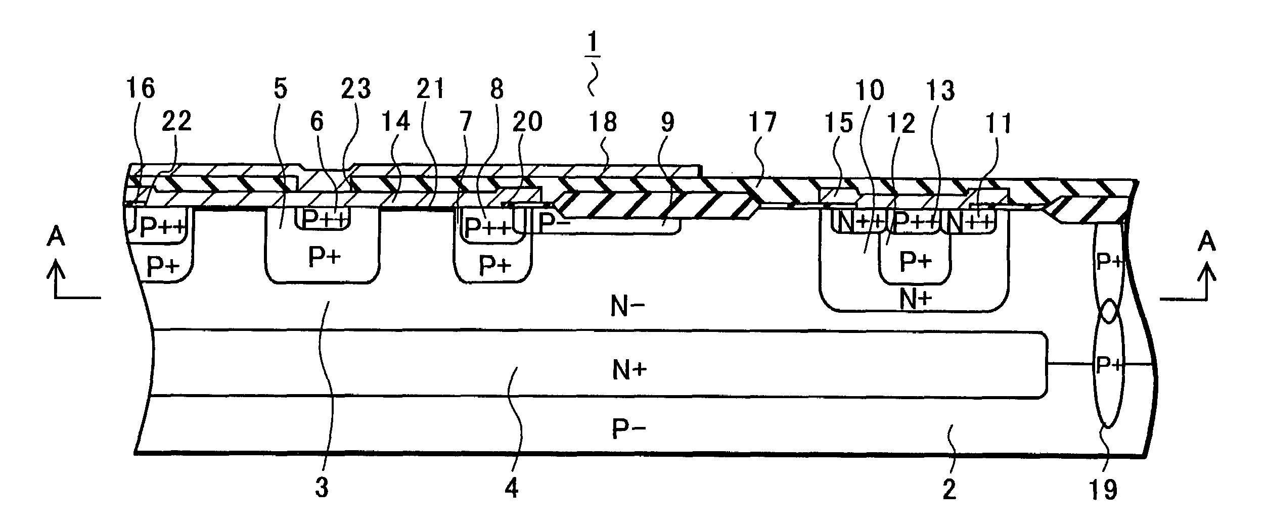
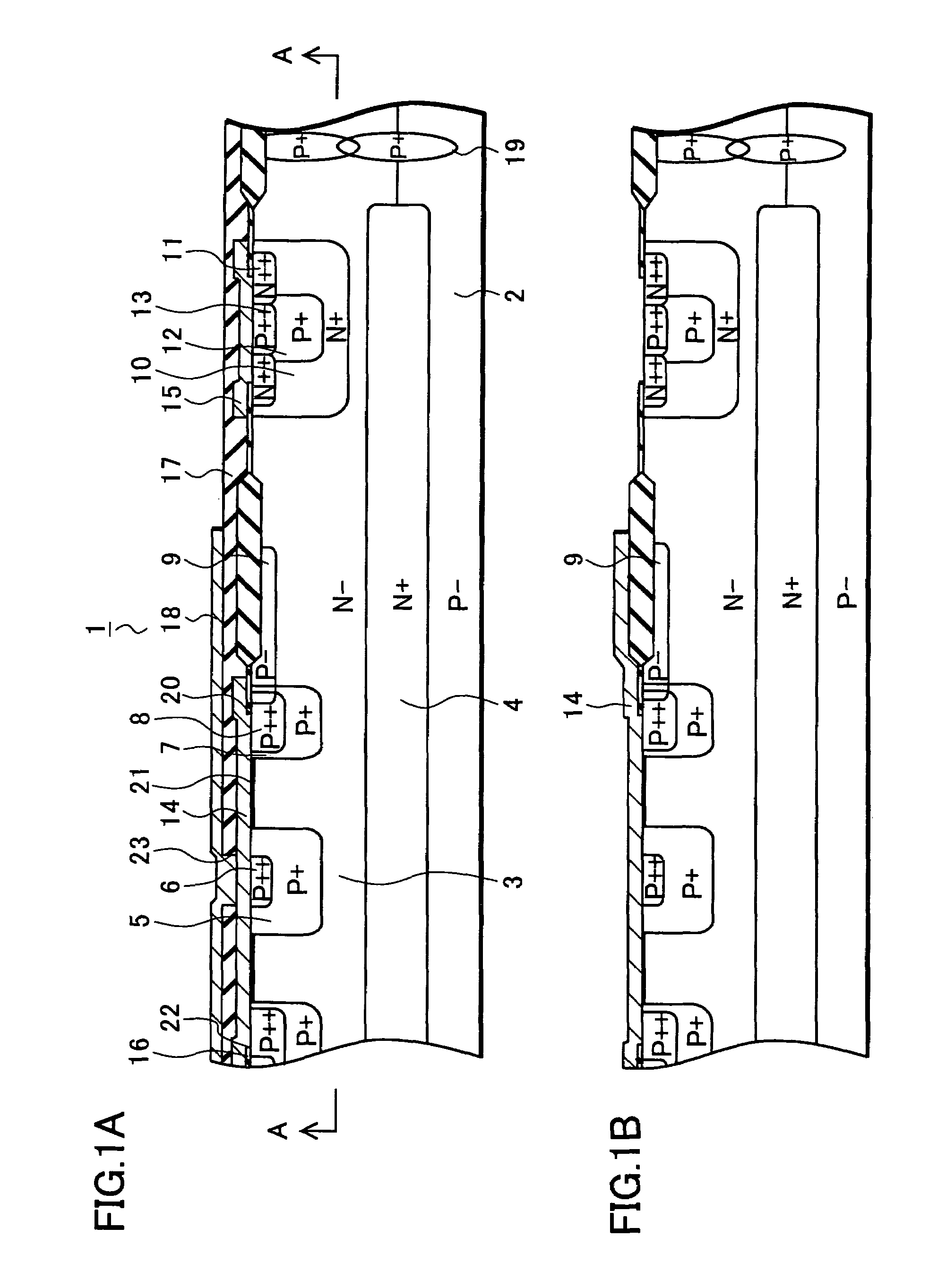
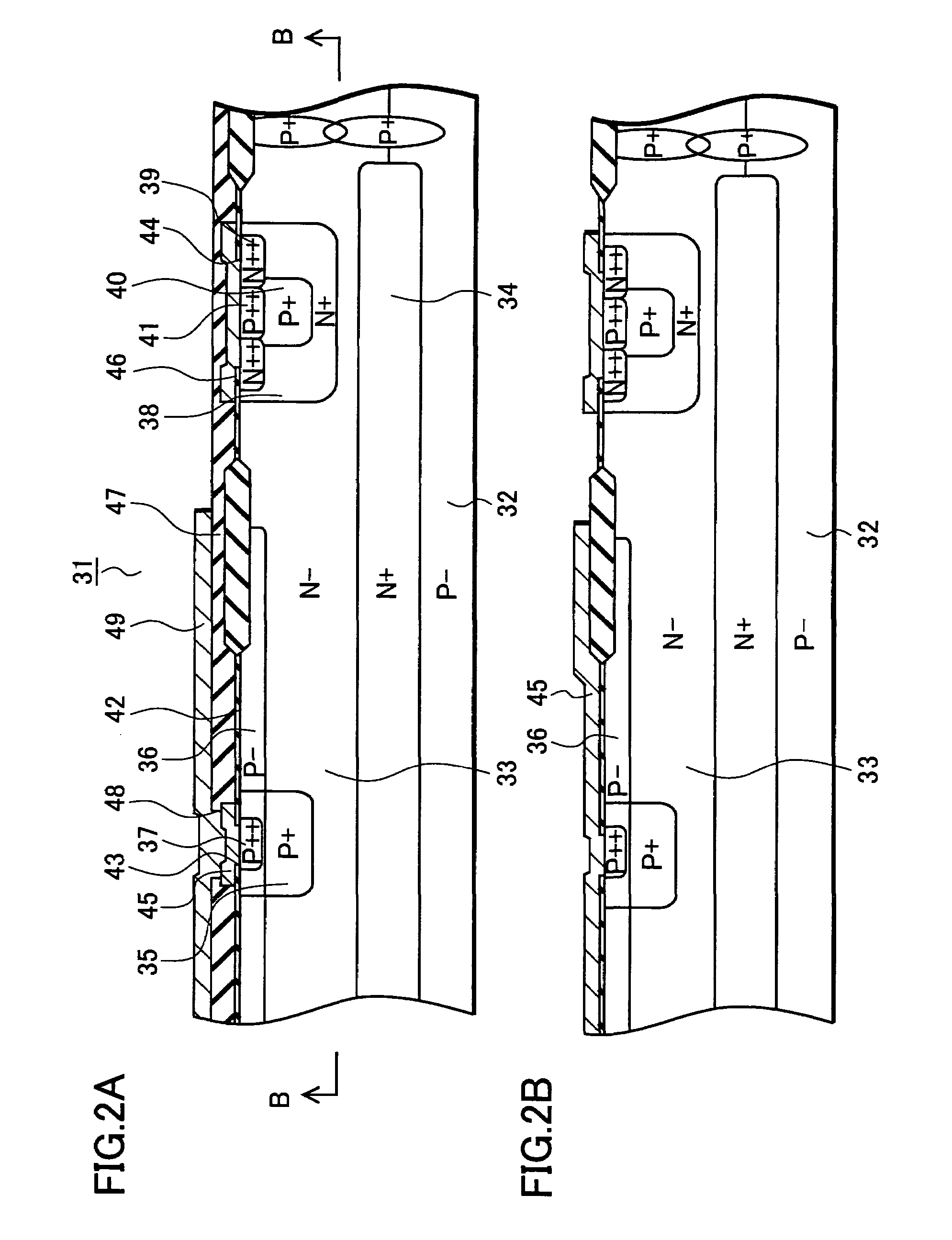
[0028]The following will specifically explain a semiconductor device according to one embodiment of the present invention with reference to FIGS. 1 to 7. FIG. 1A and FIG. 1B are cross-sectional views each explaining a protection diode according to one embodiment of the present invention. FIG. 2A and FIG. 2B are cross-sectional views each explaining a Zener diode according to the embodiment. FIG. 3 is a view explaining a forward voltage (Vf) of each of the protection diode and a Zener diode according to the embodiment. FIG. 4 is a view explaining a circuit into which the protection diode is incorporated according to the embodiment. FIG. 5A is a view explaining an electric potential distribution of the protection diode in a reverse bias state according to the embodiment. FIG. 5B is a view explaining an impact ionization occurring region in the protection diode according to the embodiment. FIG. 6 is a view explaining an electric potential distribution of the protection diode in a rever...


PUM


Abstract

In a semiconductor device of the present invention, a protection diode for protecting a device is formed on an epitaxial layer formed on a substrate. A Schottky barrier metal layer is formed on a surface of the epitaxial layer and a P-type diffusion layer is formed at a lower portion of an end portion of the Schottky barrier metal layer. Then, a P-type diffusion layer is formed to be connected to a P-type diffusion layer and is extended to a cathode region. A metal layer to which an anode electrode is applied is formed above the P-type diffusion layer, thereby making it possible to obtain a field plate effect. This structure reduces a large change in a curvature of a depletion layer, thereby improving a withstand voltage characteristic of the protection diode.

Description

[0001]Priority is claimed to Japanese Patent Application Numbers JP2005-098965, filed on Mar. 30, 2005, and JP2006-064619, filed on Mar. 9, 2006, the disclosures of which are incorporated herein by reference in its entireties.BACKGROUND OF THE INVENTION[0002]1. Field of the Invention[0003]The present invention relates to a semiconductor device that protects a circuit element from an overvoltage.[0004]2. Description of the Related Art[0005]In a conventional semiconductor device, an N-type epitaxial layer is formed on an N-type semiconductor substrate. A P-type diffusion layer is overlapped onto an N-type diffusion layer formed on the epitaxial layer. Then, an anode electrode is formed on the P-type diffusion layer, and a cathode electrode is formed on a back surface of the substrate to form a Zener diode using a PN junction of both diffusion layers. A P-type guard region is formed around the P-type diffusion layer and another guard region is formed on its outer side. A Schottky barri...

Claims


Application Information

Patent Timeline
Patent Type & Authority Patents(United States)
IPC IPC(8): H01L29/93
CPCH01L29/872H01L29/866A61F5/0102A61F5/028A61F13/148A61N2/06
Inventor KIKUCHI, SHUICHIOKAWA, SHIGEAKINAKAYA, KIYOFUMITAKAHASHI, TOSHIYUKI
Owner SEMICON COMPONENTS IND LLC
Learn More