Systems and methods of all-optical Fourier phase contrast imaging using dye doped liquid crystals

a dye-doped liquid crystal and phase contrast technology, applied in the field of phase contrast microscopy, can solve the problems of destructive interference, inability to capture the image with an ordinary camera, and difficulty in seeing with the naked eye, and achieve the effect of reducing intensity

Active Publication Date: 2010-06-15
UNIV OF MASSACHUSETTS
View PDF6 Cites 7 Cited by
  • Summary
  • Abstract
  • Description
  • Claims
  • Application Information

AI Technical Summary

Benefits of technology

[0017]Some embodiments include one or more of the following features. The lens includes a microscope objective. The optical element selected to adjust the beam intensity includes a neutral density filter. The first and second optical Fourier elements include lenses. The image sensor includes a CCD. A polarizer positioned between the second optical Fourier element and the image sensor, the polarizer being rotatable to a position selected to eliminate at least a part of the information about the sample area from the image. An optical element to direct at least part of the beam toward a fluorescence imaging system. At temperatures below the phase transition temperature, the liquid crystal molecules are birefringent, and wherein at temperatures above the phase transition temperature, the liquid crystal molecules are isotropic. The beam has a predominant polarization, and wherein the liquid crystal cell is oriented at about 45° to the predominant polarization. The liquid crystal cell further includes dye molecules selected to at least partially absorb the beam, and wherein at least partial absorption of the beam by a portion of the dye molecules heats the part of the liquid crystal molecules above the phase transition temperature. The phase transition temperature, the liquid crystal molecules are in an aligned nematic phase. The optical element is configured and arranged to adjust the beam intensity to a level at which a portion of the transformed beam transmits through the cell with a phase that is delayed relative to an other portion of the transformed beam by one of about π / 2 and about −π / 2. The portion of the transformed beam that is phase delayed corresponds to low spatial frequencies, and wherein the other portion of the transformed beam corresponds to spatial frequencies that are higher than the portion that is phase delayed and also has a lower intensity than does the portion that is phase delayed. The coherent light source includes a continuous-wave laser. The coherent light source includes a diode. The liquid crystal cell is passive, in that no voltage is applied to the cell. The optical element is further configured and arranged to adjust the beam to an intensity such that it does not damage a living organism placed in the sample area.

Problems solved by technology

Hence, these objects are very difficult to see with the naked eye and cannot be captured by an ordinary camera.
If the undeviated light is phase shifted by π / 2, then the undeviated and diffracted light arriving at the eyepiece would produce destructive interference and the object details appear dark in lighter background.
If, however, the undeviated light is phase shifted by −π / 2 then the diffracted and undeviated light beams interfere constructively.
Thus the undeviated and diffracted light interferes destructively so that the phase variations in the specimen appear bright against a dark background.
1. Halo and shade-off contrast patterns are frequently observed in phase contrast images. These observed intensity patterns do not directly correspond to the optical path difference between the specimen and the surrounding medium. The artifacts depend on both the geometrical and optical properties of the phase plate and the specimen being examined. In particular, the width and transmittance of the phase plate material play a critical role in controlling these effects. In addition, these effects are heavily influenced by the objective magnification. Apodized phase plates are used for reducing the severity of halos.
2. In order to resolve minute details and edges in the specimen, a large angle of diffracted light must be captured by the microscope objective and must be brought into a sharp focus at the image plane. The condenser aperture diaphragm opening size partially controls the coherence of the light incident on the specimen. Decreasing the opening size of the diaphragm yields greater spatial coherence but it introduces diffraction related artifacts. Thus the system is limited by the working numerical aperture of the objective thereby reducing the resolution of the instrument.
3. When the object is changed or a different magnification is desired, the bright-field image has to be obtained first and then the condenser plate has to be rotated to position the annular ring to match the new phase plate. Thus as a result of frequent rotations of the condenser plate, the annular ring tends to be out of alignment with the phase plate requiring regular maintenance of the system. Special tools are provided for adjusting the condenser plate, which require skill and experience on the part of the operator. Furthermore, rotation of the condenser plate can sometimes cause the specimen to move as it is positioned just before the condenser.
However, conventional phase contrast microscopes do not exploit advantages that come with a coherent source.
For example, the white light sources of conventional phase contrast microscopes cannot provide Fourier transformation, as a result which the object information cannot be well separated at the Fourier plane.

Method used


Image

  • Systems and methods of all-optical Fourier phase contrast imaging using dye doped liquid crystals
  • Systems and methods of all-optical Fourier phase contrast imaging using dye doped liquid crystals
  • Systems and methods of all-optical Fourier phase contrast imaging using dye doped liquid crystals

Examples


Embodiment Construction

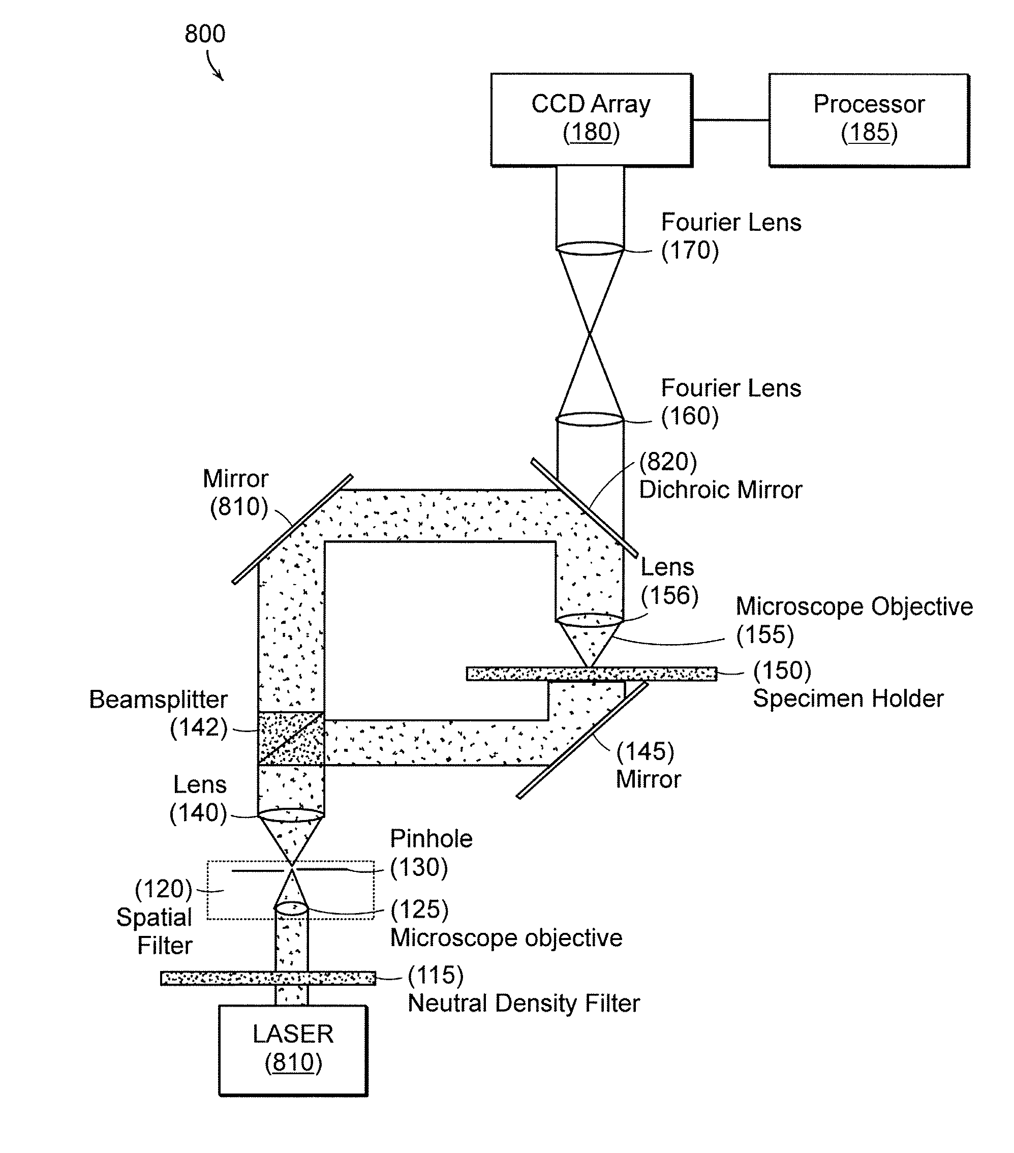
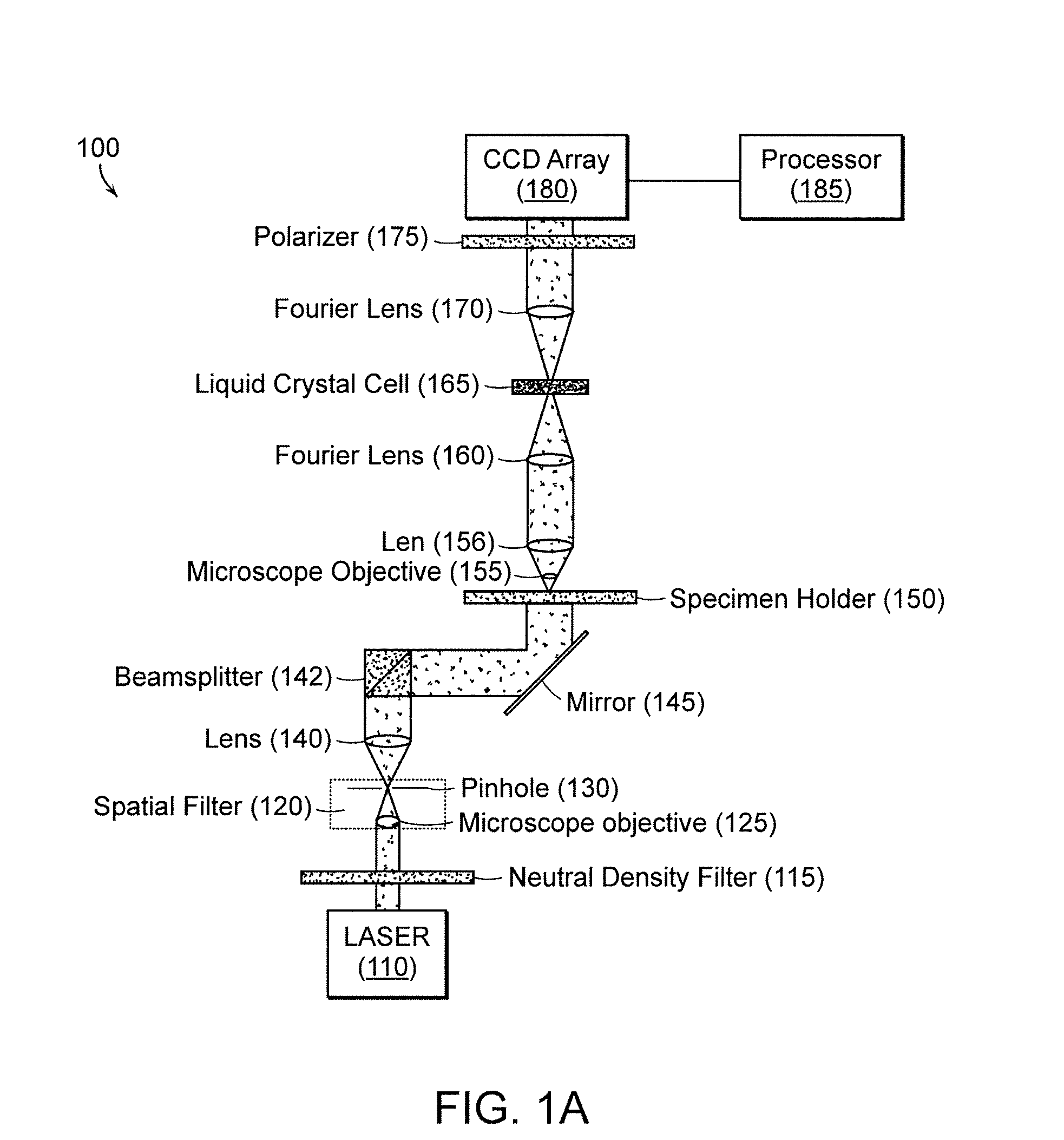
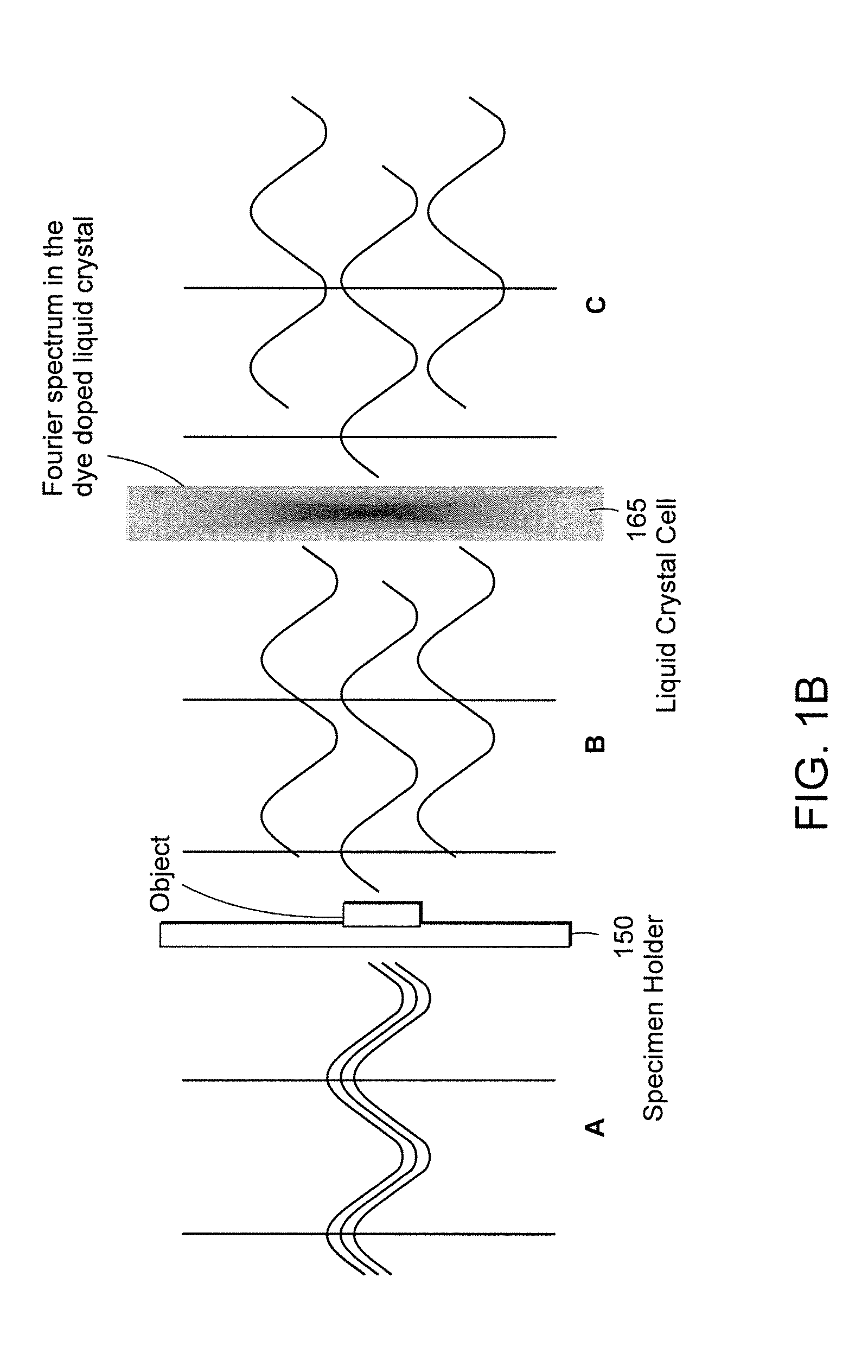
[0038]Embodiments of the invention are directed to systems and methods of all-optical Fourier phase contrast imaging using a low power coherent source (laser) and dye-doped liquid crystals. In general, the Fourier spectrum of an object contains low spatial frequencies at the center of the spectrum, with high intensities, while high spatial frequencies are on the edges, with lower intensities. The laser source provides precise separation of these frequency regimes through an all-optical Fourier transform. In some embodiments, high monochromaticity of the coherent source facilitates a well defined Fourier plane in which different spatial frequency bands are clearly resolved. In addition the intensity of the laser source makes object features bright and clearly visible. Some embodiments provide bright-field, positive phase contrast and negative phase contrast images of “phase objects,” i.e., objects that are at least partially optically transparent and thus are difficult to image using...


PUM

PropertyMeasurementUnit
wavelengthaaaaaaaaaa
path lengthaaaaaaaaaa
phase contrast imagingaaaaaaaaaa

Abstract

Under one aspect, a phase contrast imaging system includes a coherent light source emitting a coherent beam directed toward a sample area; a lens arranged to collect at least part of the beam from the sample area; an element Fourier transforming the collected beam in a Fourier plane; a liquid crystal cell in the Fourier plane that transmits at least part of the transformed beam, wherein the cell includes liquid crystal molecules having a phase transition temperature, and wherein at temperatures exceeding the phase transition temperature, light transmitted through the liquid crystal molecules obtains a different phase than light transmitted through the liquid crystal molecules obtains at temperatures below the phase transition temperature; and an element inversely Fourier transforming the transmitted beam to provide an image. Part of the transformed beam has an intensity sufficient to heat a portion of the liquid crystal molecules above the phase transition temperature.

Description

CROSS REFERENCE TO RELATED APPLICATIONS[0001]This application claims the benefit under 35 U.S.C. §119(e) of U.S. Provisional Application No. 60 / 856,972, filed Nov. 6, 2006 and entitled “Phase Contrast Imaging Using Dye Doped Liquid Crytals,” the entire contents of which are incorporated herein by reference.STATEMENT REGARDING FEDERALLY SPONSORED RESEARCH OR DEVELOPMENT[0002]This research is supported in part by a BAA contract W911QY-04-C-0063 from U.S. Army Natick Soldier Center.BACKGROUND[0003]1. Field[0004]The disclosed subject matter generally relates to phase contrast imaging, e.g., phase contrast microscopy.[0005]2. Discussion of Related Art[0006]Translucent objects or phase objects can alter only the phase of the optical wave, not its amplitude. Hence, these objects are very difficult to see with the naked eye and cannot be captured by an ordinary camera. A phase contrast microscope can be used to obtain high-contrast images of transparent specimens, such as living cells (usua...

Claims


Application Information

Patent Timeline
Patent Type & Authority Patents(United States)
IPC IPC(8): G02F1/13
CPCG02B21/14G02F1/13725G02F1/132G02B27/52
Inventor YELLESWARAPU, CHANDRA S.KOTHAPALLI, SRI RAJASEKHARRAO, D. V. GOPAL L. N.
Owner UNIV OF MASSACHUSETTS
Why Eureka
Try Eureka