
X-ray tube with transmission anode

a transmission anode and x-ray tube technology, applied in the field of x-ray tubes, can solve the problems of severe heating of the anode, limit of the x-ray tube, and melting (i.e. destruction) of the anode, and achieve the effect of improving efficiency

Inactive Publication Date: 2010-06-15
SIEMENS HEALTHCARE GMBH
View PDF9 Cites 19 Cited by
  • Summary
  • Abstract
  • Description
  • Claims
  • Application Information

AI Technical Summary

Benefits of technology

The invention is about an x-ray tube that can generate more efficient and high-quality image quality compared to existing tubes. The technical effects of the invention include a smaller focal size, higher photon flow, and better cooling of the anode. The x-ray tube uses a thin anode that is cooled at its back side with a coolant fluid directed past the anode. The efficiency of the x-ray tube is improved by optimizing the mounting of the anode and the distribution of the incident electron beam. The x-ray tube can be designed with a relatively long anode path for higher efficiency. The cathode and anode can be executed in various ways, such as annularly or segmented. The x-ray tube is at least partially constructed from ceramic material for insulation purposes.

Problems solved by technology

In CT, limits for the x-ray tube are additionally caused by its mounting in a rotating gantry with regard to cooling, weight and spatial expanse.
In order to nevertheless generate a high photon flow, a high current density must be applied to the anode, which in turn results in a severe heating of the anode and in the extreme case to melting (i.e. to destruction) of the anode.

Method used


Image

  • X-ray tube with transmission anode
  • X-ray tube with transmission anode
  • X-ray tube with transmission anode

Examples


Embodiment Construction

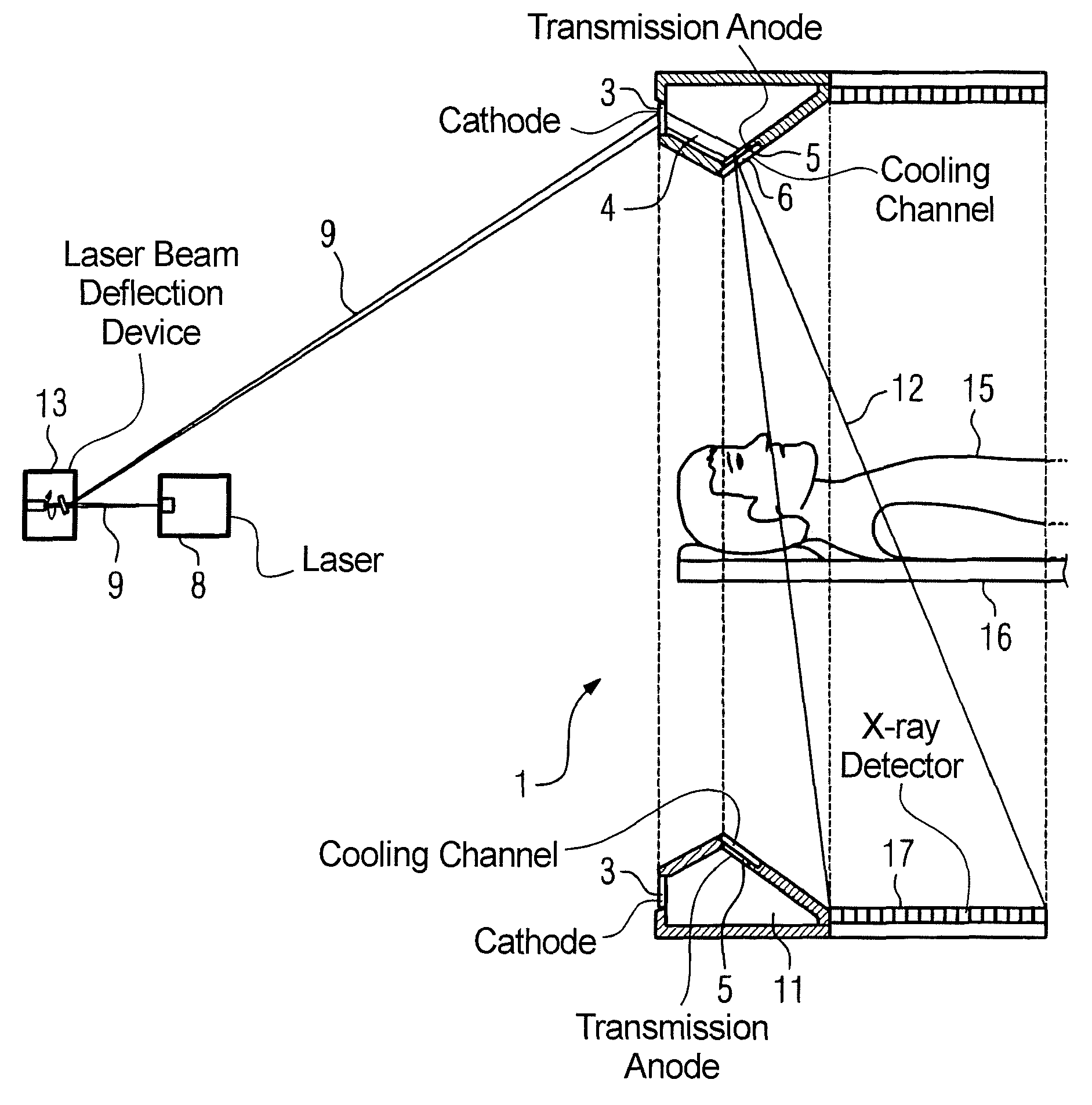
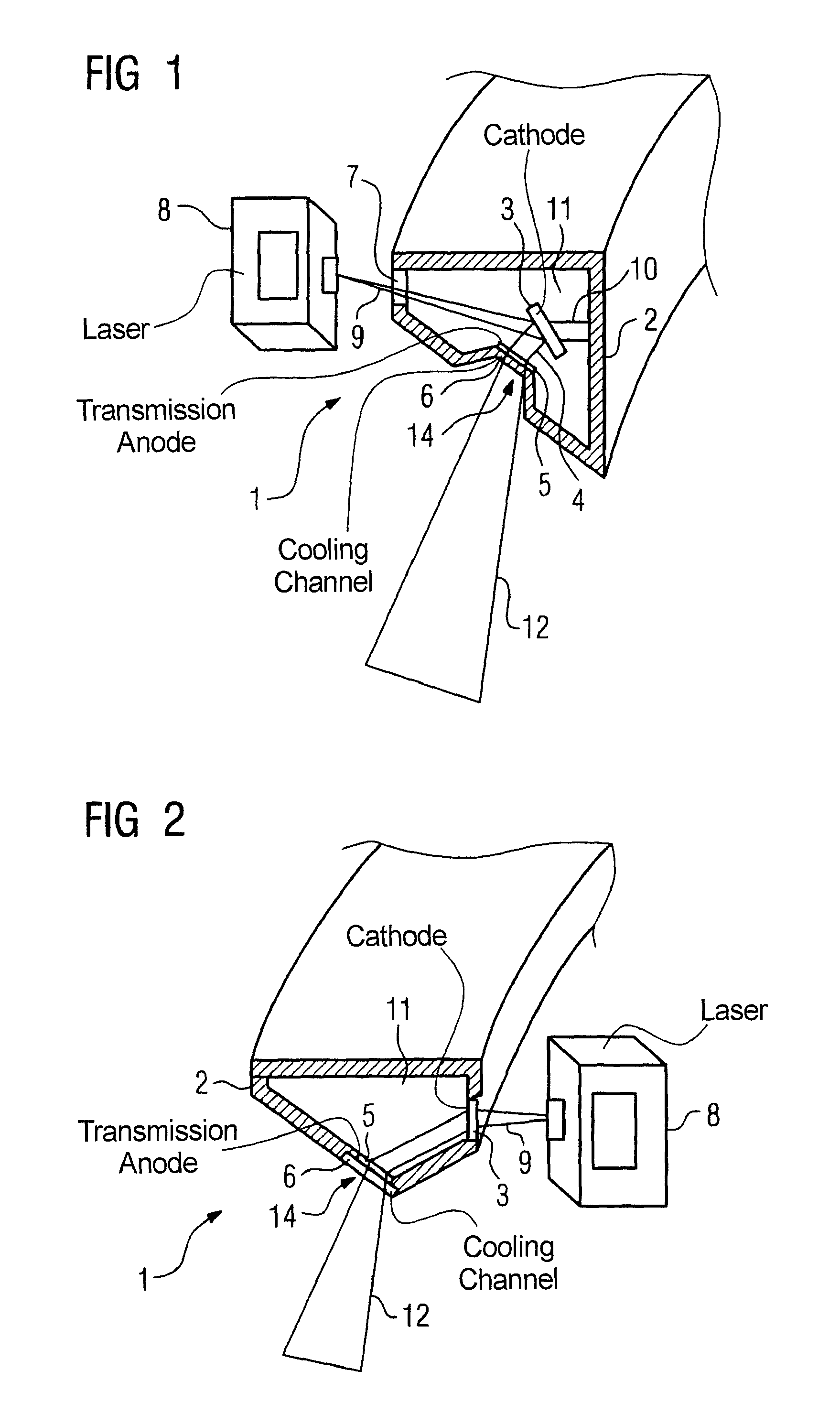
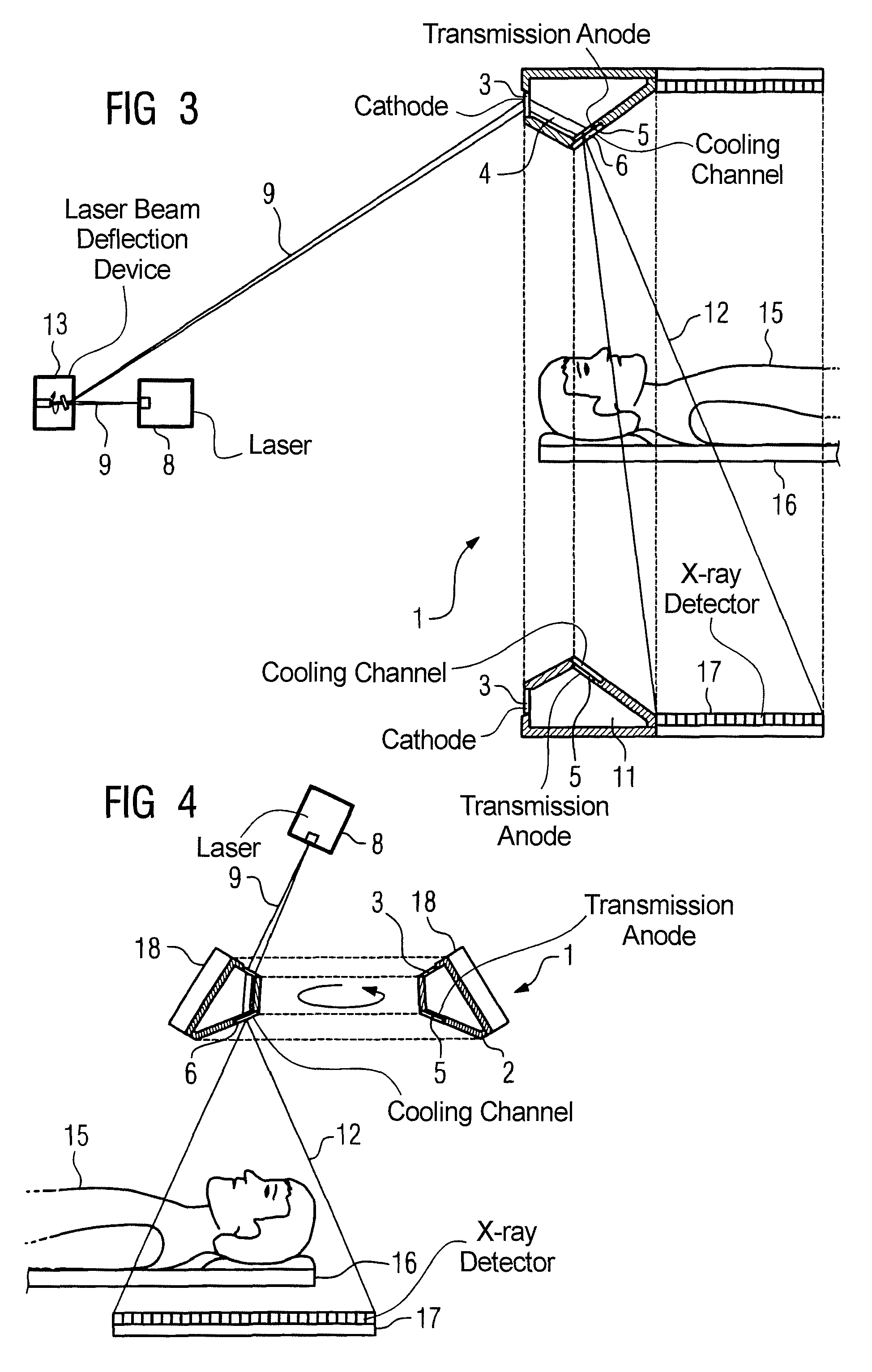
[0028]FIG. 1 shows a cross-section through an annularly designed x-ray tube 1 with a housing 2 and an optical window which enables a laser beam 9 (via a laser 8) to be applied on a cathode 3 fashioned as a frustum. The cathode 3 is connected with the housing 2 via a cathode mount 10 that is executed so as to be insulated. An electron emission that generates an electron beam 4 that strikes a transmission anode 5 arises at desired points due to the laser excitation. The transmission anode 5 is contacted by a cooling channel 6 (in which a coolant flows) on the side opposite the impact point of the electrons, such that the heat generated in the transmission anode 5 is dissipated. The x-ray radiation generated by the electron beam is limited by the transmission anode and by the cooling channel filled with coolant, which x-ray radiation is externally demarcated by an exit window 14, emitted outwardly and is available as useful (usable) x-ray radiation 12.

[0029]A similar embodiment of an x...


PUM


Abstract

An x-ray tube has a cathode that generates free electrons; an anode on which the free and accelerated electrons strikes so that x-ray radiation is generated; a cooling channel with coolant flowing therethrough to cool the anode; a vacuum region between the cathode and the anode; and an exit window through which the x-ray radiation exits from the x-ray tube. The anode is fashioned as a transmission anode; with the transmission anode arranged between the vacuum region and the cooling channel, with the cooling channel arranged between the transmission anode and the exit window; so the useful x-ray radiation passes through the coolant.

Description

BACKGROUND OF THE INVENTION[0001]1. Field of the Invention[0002]The invention concerns an x-ray tube of the type having a cathode to generate free electrons; an anode on which the free and accelerated electrons strike to cause x-ray radiation to be generated; a cooling channel with coolant flowing therethrough to cool the anode; a vacuum region between cathode and anode; and an exit window for allowing the x-ray radiation to exit from the x-ray tube.[0003]2. Description of the Prior Art[0004]An x-ray tube of this general type is known from United States Patent Application Publication 2006 / 015051 A1, for example. In this document an x-ray tube is disclosed in which a thin metal foil is used on which the electrons coming from a cathode (thus an electron source) strike with high energy and generate x-ray radiation that is directed out through a vacuum window. The thin cathode foil is cooled with the aid of a liquid. The foil is cooled on the back side, or the side facing away from the ...

Claims


Application Information

Patent Timeline
Patent Type & Authority Patents(United States)
IPC IPC(8): H01J35/06
CPCA61B6/032A61B6/4028A61B6/4488A61B6/482H01J35/08H01J35/18H01J35/065H01J2235/087H01J2235/062H01J35/116H01J35/13
Inventor POPESCU, STEFANWITTMANN, GEORG
Owner SIEMENS HEALTHCARE GMBH
Learn More