
Enhanced portable digital lidar system

a lidar and digital technology, applied in the field of portable digital lidar systems, can solve the problems of inconvenient maintenance, inconvenient operation, and inability to discriminate between biological weapon agent aerosols and other natural or interferent aerosol clouds, etc., and achieve the effect of convenient maintenance and convenient setup

Inactive Publication Date: 2010-06-22
SCI & ENG SERVICES
View PDF11 Cites 38 Cited by
  • Summary
  • Abstract
  • Description
  • Claims
  • Application Information

AI Technical Summary

Benefits of technology

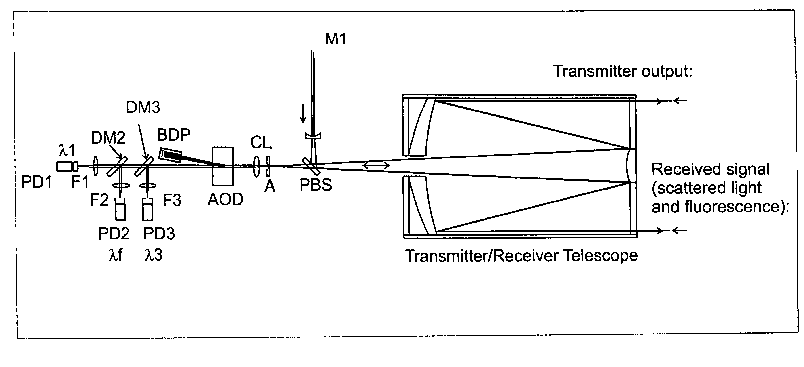
"The present invention is a detection system for airborne agents that can be used for civilian and military applications. The system includes a laser source, a transmitter, and a coupling mechanism to remotely couple the laser pulses to the transmitter. The system also includes a detection system with optical detectors to detect both elastically backscattered signals and fluorescence signals from the airborne agents. The invention has the following technical effects: easy setup in the field, eye-safe, operates autonomously, detects, tracks, and discriminates bio-aerosol clouds, is modular for easy maintenance, provides an adequate response time, integrates multiple analysis techniques to reduce false alarms, improves reliability in the field, and improves signal-to-noise ratios and detected signals through digital detection. The invention also includes a special detachable fiber optic system that facilitates maintenance and servicing of the laser and transportation."

Problems solved by technology

However, single wavelength aerosol lidars, as currently employed, do not provide discrimination between biological weapon (BW) agent aerosols and other natural or interferent aerosol clouds.
However, the elastic scattering technique lacks the required specificity for deterministic application of the data in the battle field.
However, present technologies, owing to the complexity and laser power levels required for fluorescence and aerosol lidar, are limited in range and not well suited for an in-the-field, portable early warning detection system.

Method used


Image

  • Enhanced portable digital lidar system
  • Enhanced portable digital lidar system
  • Enhanced portable digital lidar system

Examples


Embodiment Construction

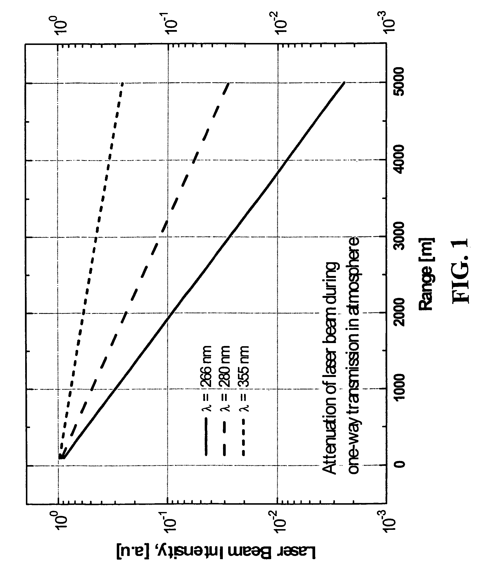
[0032]Referring now to the drawings, wherein like reference numerals designate identical or corresponding parts throughout the several views, and more particularly to FIG. 1 thereof, FIG. 1 shows at three wavelengths (i.e., 266, 280 and 355 nm) the reduction in the laser beam intensity due to scattering and absorption by atmospheric constituents as the laser beam travels to a target. Difference in the fluorescence between excitation at 266 nm and 355 nm is more than compensated by the difference in the atmospheric transmittance shown in FIG. 1. From the lidar signal considerations shown in FIG. 1, even with a 100-fold smaller fluorescence cross section, the 355 nm lidar is an exemplary wavelength of choice for the present invention.

[0033]In fluorescence lidar, autofluorescence excited by a UV laser from biological cells is utilized to identify the fluorescing biological cells from other non-biological or naturally occurring particles. Naturally fluorescent aromatic amino acids resid...


PUM


Abstract

A system for detecting airborne agents. The system can include a laser source that provides laser pulses of at least two wavelengths, a transmitter that transmits the laser pulses, and a coupling mechanism configured to remotely couple the laser pulses between the laser source and the transmitter. The system can include a receiver receives both elastically backscattered signals from airborne agents and fluorescence signals from the airborne agents. The system can include a telescope both transmits a collimated laser beam of the laser pulse from the transmitter to a far field and receives the elastically backscattered signals and the fluorescence signals from the far field. The system can include a detection system having at least one of a backscatter optical detector that detects the elastically backscattered signals and one or more fluorescence optical detectors that detect the fluorescence signals in selected spectral band(s) from the airborne agents.

Description

CROSS REFERENCE TO RELATED APPLICATIONS[0001]This application is related to U.S. patent application Ser. No. 09 / 852,782 entitled “Portable Digital Lidar (PDL)”, filed on May 11, 2001, now U.S. Pat. No. 6,593,582 B2, the entire contents of which are incorporated herein by reference. This application is related to U.S. patent application Ser. No. 10 / 146,920 entitled “A Method of Coupling a Laser Signal to an Optical Carrier”, filed on May 17, 2002, the entire contents of which are incorporated herein by reference now published as U.S. Pat. Application Publication No. US 2003 / 0215181 A1. This application is related to and claims priority under 35 U.S.C. §119(e) to U.S. Ser. No. 60 / 628,925, the entire contents of which are incorporated herein by reference.BACKGROUND OF THE INVENTION[0002]1. Field of the Invention[0003]The present invention relates to a portable light detecting and ranging (LIDAR) system used, for example a for long-range detection of biological weapon (biological warfar...

Claims


Application Information

Patent Timeline
Patent Type & Authority Patents(United States)
IPC IPC(8): G01J1/58
CPCG01N21/645G01N21/6486G01S17/95G01S7/481G01S7/4815G01S7/4817G01S17/88G01N2021/1793G01N2021/4709G01N2021/6476Y02A90/10
Inventor LEE, HYO SANGHWANG, IN HEONPRASAD, COORG R.
Owner SCI & ENG SERVICES
Learn More