Pressure sensor for extracorporeal circulating circuit

a technology of circulating circuit and pressure sensor, which is applied in the direction of fluid pressure measurement by mechanical elements, instruments, measurement devices, etc., can solve the problems of long time, retention or coagulation, and the inability to allow the air chamber, so as to achieve small measurement error and detect pressure

Inactive Publication Date: 2010-07-06
ASAHI KASEI MEDICAL CO LTD
View PDF23 Cites 17 Cited by
  • Summary
  • Abstract
  • Description
  • Claims
  • Application Information

AI Technical Summary

Benefits of technology

[0020]Another object of the present invention is to provide a pressure sensor for measuring a pressure in an extracorporeal circulating circuit without contacting a liquid to with air wherein the pressure sensor can measure a pressure even when the pressure is changing, does not require an increase of the volumes of an air chamber and a liquid chamber, and can detect pressure with small measurement error using one type of pressure sensor without controlling of the volume of air on the air chamber side.
[0156]Moreover, a pressure sensor of the present invention is able to detect damage of the flexible diaphragm of the pressure sensor, and ensures safety as a pressure sensor. Thus, in an extracorporeal circulation therapy in which blood is pulled out of the body of a patient for an extracorporeal treatment by a blood processing apparatus and the blood is returned into the body after the treatment, a pressure sensor of the present invention can safely measure a pressure in an extracorporeal circulating circuit. Therefore, a pressure sensor of the present invention can be usefully used in extracorporeal circulation treatment. Furthermore, a pressure sensor of the present invention surely detects the connection between a casing of the pressure sensor and an attachment surface. Thus, in an extracorporeal circulation therapy in which blood is pulled out of the body of a patient for an extracorporeal treatment by a blood processing apparatus and the blood is returned into the body after the treatment, a pressure sensor of the present invention can safely measure a pressure in an extracorporeal circulating circuit. Therefore, a pressure sensor of the present invention can be usefully used in extracorporeal circulation treatment.

Problems solved by technology

Thus, it takes a long time to exchange the stored liquid with a liquid to be newly introduced, which may cause retention or coagulation of the body fluid or medicinal solution.
This does not allow the air chamber 9 to have a smaller volume.
Furthermore, the deformable plane 20 in the pressure sensor 3 in the prior art as shown in FIG. 34 may be damaged due to the soft material thereof.
In case of damage of the deformable plane, the operation is just like the pressure measuring method using the drip chamber shown in FIG. 33, and cannot avoid the above described problems of coagulation due to the contact between the air and the body fluid or medicinal solution.
This causes the differences between the pressure characteristics obtained in the case where a pressure is measured via air and in the case where a pressure is measured via the deformable plane, thereby resulting in a problem that no pressure can be correctly measured.
Therefore, if there is any incomplete connection, the leakage between the pressure sensor and the pressure measuring means is caused, thereby making it impossible to correctly measure a pressure therein.
However, the hydraulic measuring apparatus shown in FIG. 35 needs to have a pump, a valve, and separate pressure measuring means mounted thereto, in addition to a pressure sensor which measures a pressure, which inevitably makes the configuration of the apparatus complicated and in turn causes an increased cost of the apparatus.
Furthermore, in order to perform a stable pressure measurement, the volume of air in the air chamber should be strictly controlled, which causes the problem that the control requires tremendous accuracy.Patent Document 1: JP-A-2002-282355Patent Document 2: JP-A-09-024026Patent Document 3: JP-A-08-117332

Method used


Image

  • Pressure sensor for extracorporeal circulating circuit
  • Pressure sensor for extracorporeal circulating circuit
  • Pressure sensor for extracorporeal circulating circuit

Examples


example

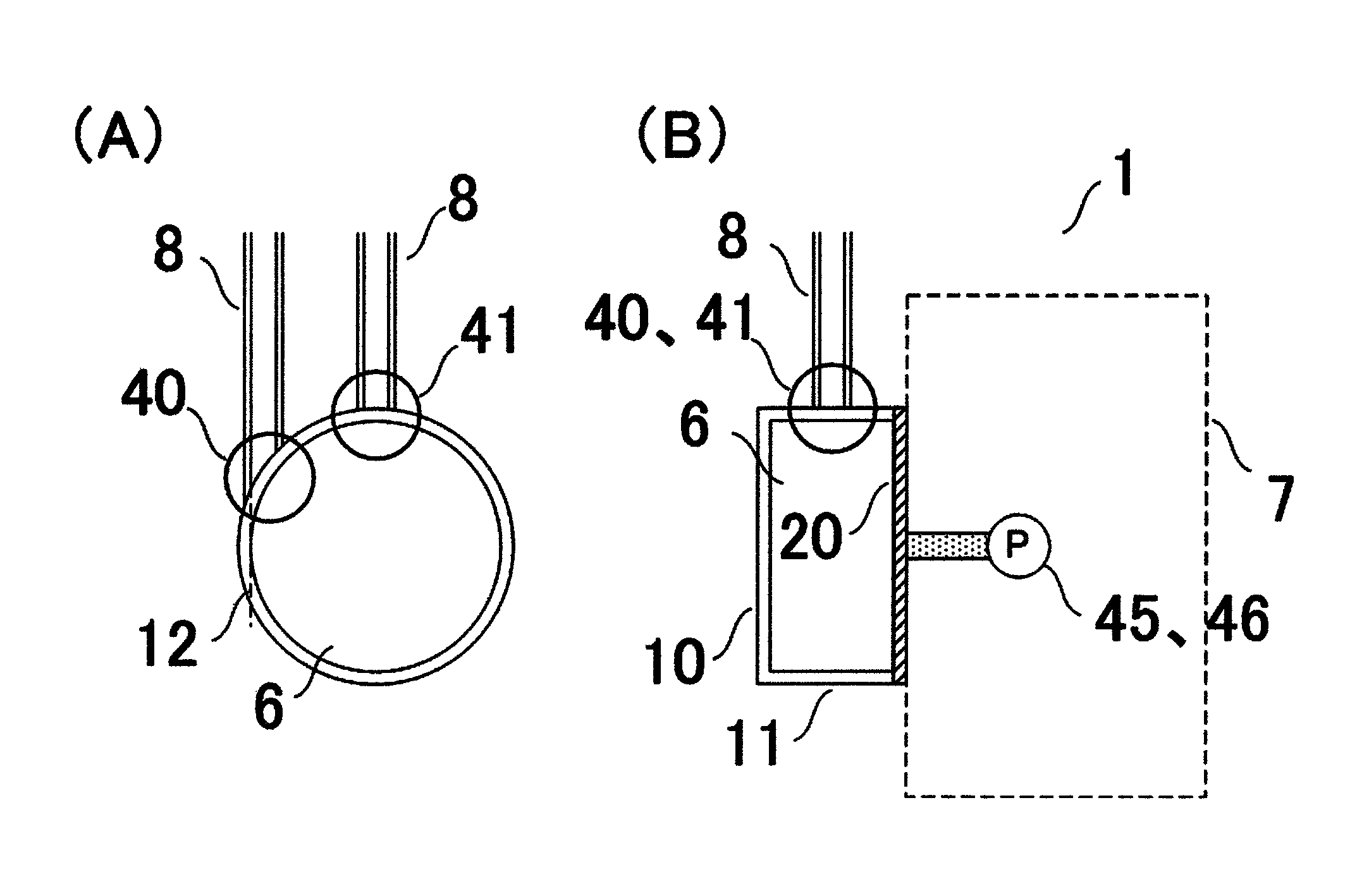
[0148]Now, the following is the explanation of a confirmation of effect obtained by the present invention by way of the examples. The pressure sensors having the configuration shown in FIG. 1 (first embodiment) and FIG. 34 (comparative example 1) were used to perform a comparative test about displacement efficiency of liquid, by the following method:[0149](1) Tap water which was colored to orange-red was used as a first liquid that flows through the liquid flow path 8 and the pressure sensor 1, and a liquid feed pump was used to supply the tap water at a rate of 50 ml / min to fill the liquid flow path 8 and the pressure sensor 1;[0150](2) Next, clear tap water was used as a second liquid that flows through the liquid flow path 8 and the pressure sensor 1, and a liquid feed pump was used to supply the tap water at the same rate of 50 ml / min; and[0151](3) The period of time from when the supplying of the second liquid was started until the water in the casing of the pressure sensor 1 b...

first embodiment

[0152]The liquid flow path 8 was provided by individually connecting tubes of soft polyvinyl chloride having an inner diameter of 3.3 mm to the inlet side and the outlet side of the pressure sensor 1, and placing a peristaltic pump on the circuit on the inlet side as a feed pump. A test was performed using the reference plane 10 and the deformable plane 20 having a diameter of 20 mm, the liquid flow path 8 of FIG. 1 with the first connecting plane having a height of 10 mm, and the pressure sensor 1. The reference plane 10, the deformable plane 20, and the connecting plane 11 were individually formed of polycarbonate. Because the purpose of the test was to measure displacement efficiency and no measurement of pressure was performed, the deformable plane 20 was entirely formed of polycarbonate, and no section which is deformable (deformable section) was provided thereto. As a result of the test, it required 120 seconds to displace the water in the casing with clear tap water.


PUM

PropertyMeasurementUnit
pressureaaaaaaaaaa
pressureaaaaaaaaaa
pressureaaaaaaaaaa

Abstract

A pressure sensor for an extracorporeal circulating circuit includes a liquid chamber, a pressure measuring means, and a liquid flow path. The liquid chamber includes a reference surface not deformed by a pressure in the extracorporeal circulating circuit, a deforming surface disposed separated from the reference surface and deformed at least partially by a pressure in the extracorporeal circulating circuit, a first connection surface that joins the deforming surface with the reference surface to form a closed liquid-tight space inside them and is not deformed by a pressure in the extracorporeal circulating circuit, a liquid inflowing port provided in the side surface of the first connection surface, and a liquid outflowing port disposed away by ½ to less than one round from the inflowing port in the flowing direction of liquid introduced along the inner periphery of the side surface of the first connection surface. The pressure measuring means measures the deformation amount of the deforming surface, and is disposed outside the liquid chamber; and the liquid flow path is liquid-tightly connected with the liquid inflowing port so that liquid to be introduced into the liquid chamber flows in along the inner periphery of the side surface of the first connection surface.

Description

TECHNICAL FIELD[0001]The present invention relates to a pressure sensor for measuring a pressure in an extracorporeal circulating circuit which causes a liquid, specifically body fluid or medicinal solution to flow therein.BACKGROUND ART[0002]In an extracorporeal circulation therapy in which blood is pulled out of the body of a patient for an extracorporeal treatment by a blood processing apparatus and the blood is returned into the body after the treatment, usually, a pressure sensor is provided to measure a pressure in the extracorporeal circulating circuit. As an example of the means for measuring a pressure in an extracorporeal circulating circuit, Patent Document 1 describes a pressure measuring method using a drip chamber which is commonly used in an extracorporeal circulation therapy.[0003]FIG. 33 is a schematic configuration view showing an example of a pressure measuring method using a drip chamber. As shown in FIG. 33, a drip chamber 2 is disposed in the middle of a liquid...

Claims


Application Information

Patent Timeline
Patent Type & Authority Patents(United States)
IPC IPC(8): G01L7/00
CPCA61M1/3639A61M1/3641G01L19/00A61M1/00
Inventor KOUDA, MASAAKIKOBAYASHI, KENGO
Owner ASAHI KASEI MEDICAL CO LTD
Why Eureka
Try Eureka