
Multilayer braze-able sheet

a multi-layer brazing and sheet technology, applied in the direction of solventing apparatus, manufacturing tools, other domestic objects, etc., can solve the problems of poor post-brazing performance, poor post-brazing strength, and poor post-brazing strength, so as to reduce aging time, improve post-brazing strength, and maintain corrosion resistance

Inactive Publication Date: 2010-07-06
ARCONIC TECH LLC +1
View PDF22 Cites 9 Cited by
  • Summary
  • Abstract
  • Description
  • Claims
  • Application Information

AI Technical Summary

Benefits of technology

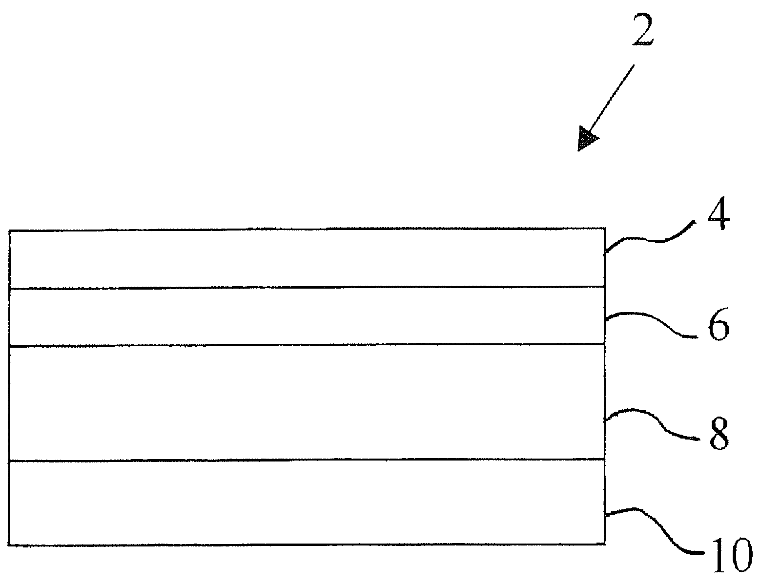
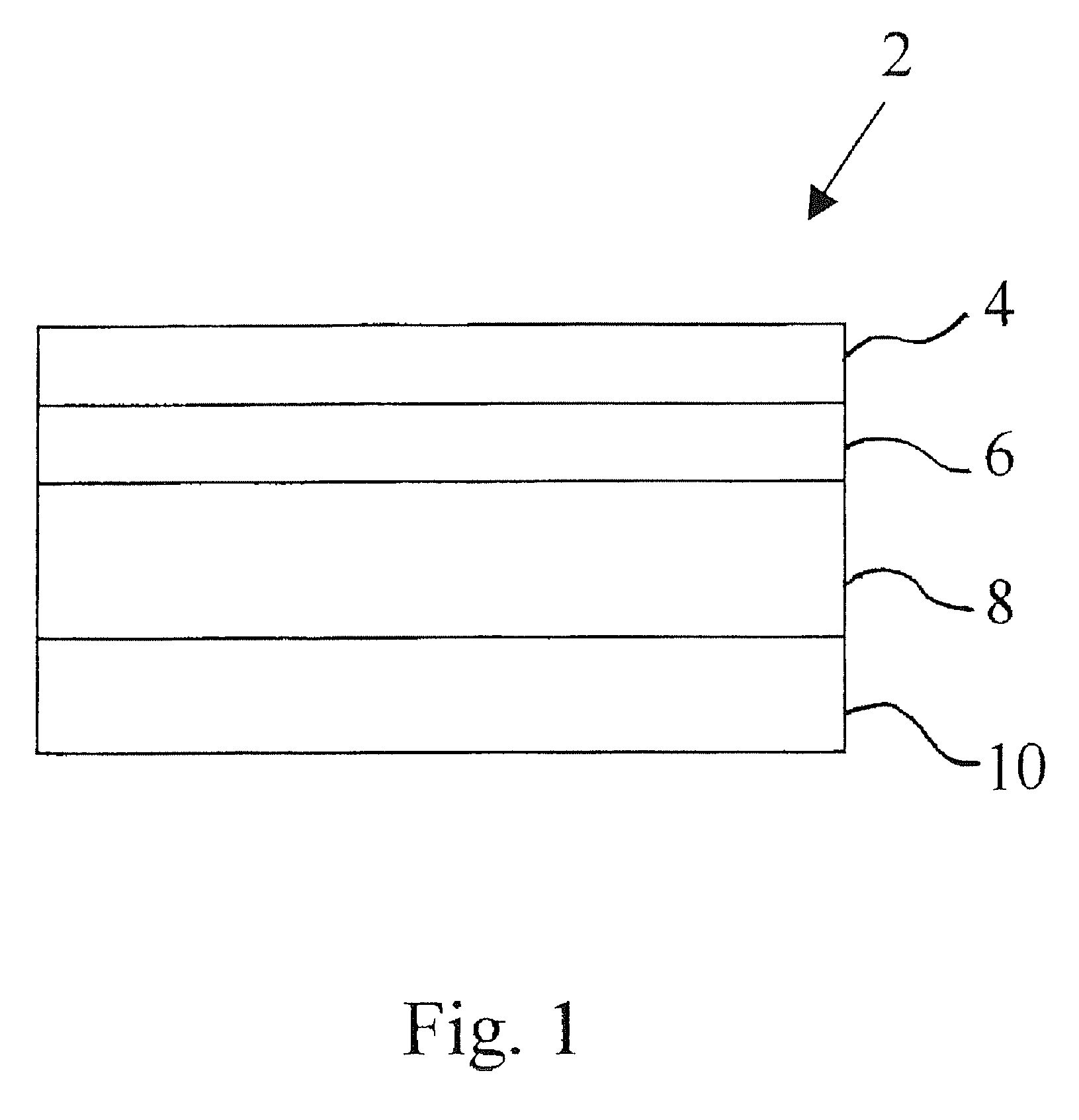
The present invention provides a multi-layered brazing sheet that includes an interliner and a braze clad layer, as well as a sacrificial layer. The brazing sheet is made from an aluminum alloy that includes specific amounts of copper, silicon, manganese, iron, and other elements. The brazing process involves heating the brazing sheet to a high temperature and then cooling it quickly. The brazing sheet can be used to join aluminum parts together with increased strength and decreased aging time. The technical effects of this invention include improved post-braze strength and corrosion resistance.

Problems solved by technology

It is well known, however, that combinations of solutes in aluminum can result in precipitation hardening under certain conditions of concentration and thermal history.
While Si is a common element in aluminum braze alloys and is often present in the AA3XXX alloys commonly used as the core layer of aluminum brazing sheet, Mg is often restricted in brazing alloys used in the CAB process.
This is due to the known detrimental effect Mg has on Nocolok® type fluxes.
Mg interacts with the flux in a way that has a negative impact on brazing performance.
If Mg is present in the core layer in high enough concentrations (sometimes even as little as 0.1% can be detrimental) it can diffuse into a braze liner during the CAB process to interact with the flux.
However, for B-tube configurations, the use of a high Mg sacrificial layer will interfere with good braze joint formation at locations where the braze filler metal needs to wet the internal sacrificial layer.

Method used


Image

  • Multilayer braze-able sheet
  • Multilayer braze-able sheet

Examples


example 1

[0039]Table 1 below shows compositions of components, namely core layers, interliners and sacrificial layers, from which 4-layer composite tubestock brazing sheets were fabricated. The components were fabricated in accordance with the invention, with the exception of interliner designated AIL1, which had low copper.

[0040]

TABLE 1Desig-ComponentnationSiFeCuMnMgTiZnCoreAC10.920.180.781.20.560.150AC20.890.180.911.530.590.150KC10.830.841.610.380.140InterlinerAIL10.760.20.221.1900.160AIL20.790.190.521.5600.160KIL30.870.841.5700.140KIL41.010.941.600.130SacrificialAS10.810.1801.000.0034.05AS20.820.180.011.2100.0094.06KS30.870.984.54KS40.991.24.98

[0041]As shown in Table 2, brazing sheet composites were fabricated from the above components. Composites A, B and C were fabricated at 200 micron thickness. Composite D, which did not conform to the present invention because of the low Cu content of component AIL1, was fabricated at 150 micron thickness. The difference in thickness of composite D r...


PUM

PropertyMeasurementUnit
thicknessaaaaaaaaaa
thicknessaaaaaaaaaa
ultimate tensile strengthaaaaaaaaaa

Abstract

A multi-layer aluminum brazing sheet including a core layer, interliner, braze clad layer and a sacrificial layer, in which the post-braze strength of the brazing sheet is optimized by controlling the manganese (Mn), silicon (Si), copper (Cu) and magnesium (Mg) contents of the core layer and the Mn, Si and Cu content of the interliner and the Mn, Si and Zn content of the sacrificial layer and the specifics of the braze thermal cycle. The brazing sheet maintains corrosion resistance, while optimizing post-braze strength, by utilizing 0.5 wt. % to 1.2 wt. % Cu in the interliner. Further, the interliner and sacrificial layer of the brazing sheet contain low or no magnesium to maintain the brazing sheet's braze-ability.

Description

FIELD OF THE INVENTION[0001]The invention relates to a multiple layer brazing sheet that is braze-able with a controlled atmosphere brazing process using a fluoride based flux and provides improved post braze strength while maintaining the corrosion resistance of the sheet.BACKGROUND OF THE INVENTION[0002]Joining of aluminum by brazing is a well known process due to the strong and uniform joints that can be produced between aluminum parts of varying shapes and types. A commercially important brazing process today is the Controlled Atmosphere Brazing process hereinafter the CAB process. As the name implies, the CAB process is performed in a furnace with a controlled atmosphere having low oxygen and moisture content to minimize oxidation of aluminum at elevated temperatures. In the CAB process, aluminum parts to be joined are formed, sometimes cleaned, fluxed and then brazed at temperatures close to 600° C. The CAB process requires melting of a filler metal, typically a 4XXX series (A...

Claims


Application Information

Patent Timeline
Patent Type & Authority Patents(United States)
IPC IPC(8): B32B15/20
CPCB32B15/016C22C21/02C22C21/10C22C21/16C22C21/14Y10T428/12764Y10S165/905Y10S428/933
Inventor KOSHIGOE, FUMIHIROTSURUNO, AKIHIROUEDA, TOSHIKIBAUMANN, STEPHEN F.
Owner ARCONIC TECH LLC
Learn More