Tubing preparation machine

a tubing and tubing cutting technology, applied in the field of tubing cutting and cleaning, can solve the problems of repetitive stress type disability claims, higher overall job cost, and operator injury, and achieve the effects of less physical fatigue, safe and fast tubing cutting process, and less effort for the operator

Active Publication Date: 2010-07-13
FRUZZETTI JR FRANCIS PAUL +1
View PDF21 Cites 19 Cited by
  • Summary
  • Abstract
  • Description
  • Claims
  • Application Information

AI Technical Summary

Benefits of technology

[0019]It is another object of the invention to provide a safe, fast and accurate cutting process of tubing, which requires no reaming or deburring of the cut end of the tubing, and only minimal effort on the part of the operator, resulting in less physical fatigue to the operator and higher productivity.
[0020]It is another object of the invention to provide a safe, fast and thorough cleaning process of tubing and fittings, requiring minimal effort on the part of the operator.
[0021]It is another object of the invention to have the capability of cleaning various size tubing and fittings with the ability to reverse the rotation of the cleaning brushes and therefore substantially increase the life expectancy of the cleaner brushes.
[0022]In accordance with the present invention, a tubing preparation machine is provided for the cutting and cleaning of tubing and related fittings which substantially reduces the time and physical effort required by the operator to accomplish this task. The present invention is an electrically powered (i.e., alternating current or direct current) mechanical device which provides for the cutting and cleaning of tubing and related fittings all located in one convenient and portable housing assembly. The housing assembly contains a cutoff assembly that virtually eliminates the need for the reaming and deburring of the cut end of the tubing. A cleaner assembly is also provided that has a tubing alignment guide with a concave relief and integral tubing alignment guide reliefs that accept the tubing to the correct depth for cleaning while stabilizing the tubing during the cleaning process. A quick release chuck allows the operator to easily attach the correct size fitting cleaner brush. The present invention is portable, lightweight and easily hand carried by the operator to the work site by use of a handle provided on the housing assembly cover.

Problems solved by technology

The most common method used today for the cutting of tubing and the cleaning of the tubing and fittings requires a time-consuming, laborious and highly repetitive procedure which can result in stress related injury to the operator.
This most common method used today also results in higher overall job cost as well as higher job related disability claims.
The adjustable mechanical style tubing cutter such as the Ridge Tool Company Model 15, relies upon the physical exertion of the operator, which is labor intensive and over time will result in repetitive stress type disability claims.
In addition to being labor intensive, the mechanical method is a slow and time-consuming process.
The use of sand cloth for cleaning the exterior of tubing, such as the William H. Harvey Company, Model No. 095705, also relies upon the physical exertion of the operator and results in repetitive stress type injuries and disability claims.
In addition to being labor intensive, the use of sand cloth is a slow and time-consuming process.
The use of a hand held tool for the reaming and deburring of tubing, such as the Ridge Tool Company, Model No. 227, and the use of a hand held fitting brush for cleaning the interior of fittings, such as the Oatey Company, Model No. 31328, are subject to the same problems mentioned hereinabove.
The addition of an abrasive to the standard cutter merely compounds the already identified disadvantages of the mechanical style tubing cutter.
Such tools either do not include all of the operations necessary for the preparation of the tubing and related fittings to be joined, or they are cumbersome for the operator to use.
As a result they could also cause repetitive stress type injury or disability and could pose a substantial safety hazard to the operator or others in close proximity.
However, the Ridgid Model 122 also has inherent disadvantages: (1) weight of the unit makes portability difficult; (2) usability is restricted because the unit operates only on an alternating current power source; (3) set up of the machine requires that the unit be bolted to a bench (the Operator's Manual states, “failure to place machine on a stable bench may result in tipping and serious injury”); (4) a single on / off switch energizes the motor, which in turn drives the tubing rollers, the tubing cleaner brush, the reamer and the fitting cleaner brush, all moving simultaneously (the Operator's Manual states, “Clothing can be caught in rotating rollers or tools,”“Hand or fingers can be cut by rotating reamer,” and “Keep electrical cord away from reamer and wire brushes”); (5) the tubing is spinning during the cutting process (the Operator's Manual states, “Do not cut visibly bent tubing” and “Cutting bent tubing will result in excessive vibration, use hand cutter”); (6) since this machine uses a standard cutting wheel, the cut tubing still requires the reaming and deburring process; (7) short pieces of tubing cannot be safely cleaned by the operator because of the exposed wire wheel and the close proximity of the operator's hands to the wire wheel.

Method used


Image

  • Tubing preparation machine
  • Tubing preparation machine
  • Tubing preparation machine

Examples


Embodiment Construction

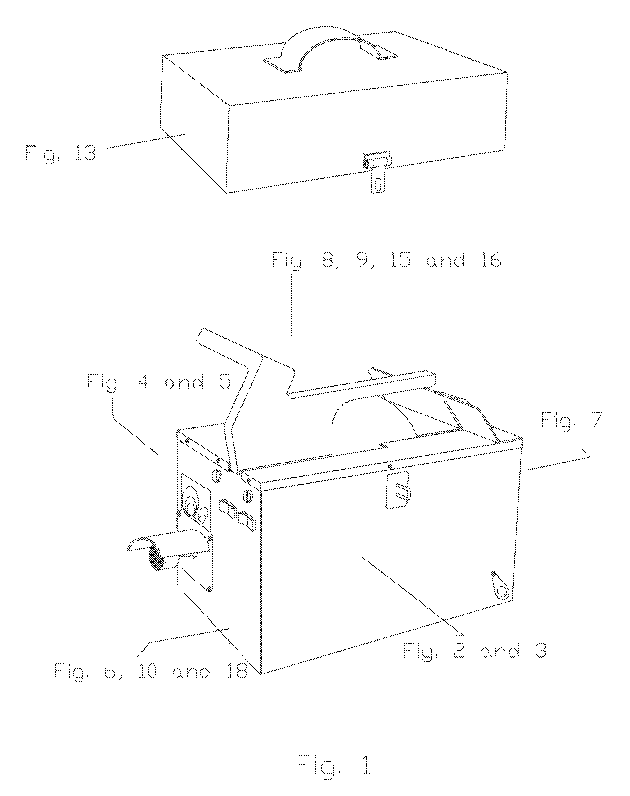
[0043]FIG. 1 is a perspective view of an embodiment of the present invention, a tubing preparation machine 300.

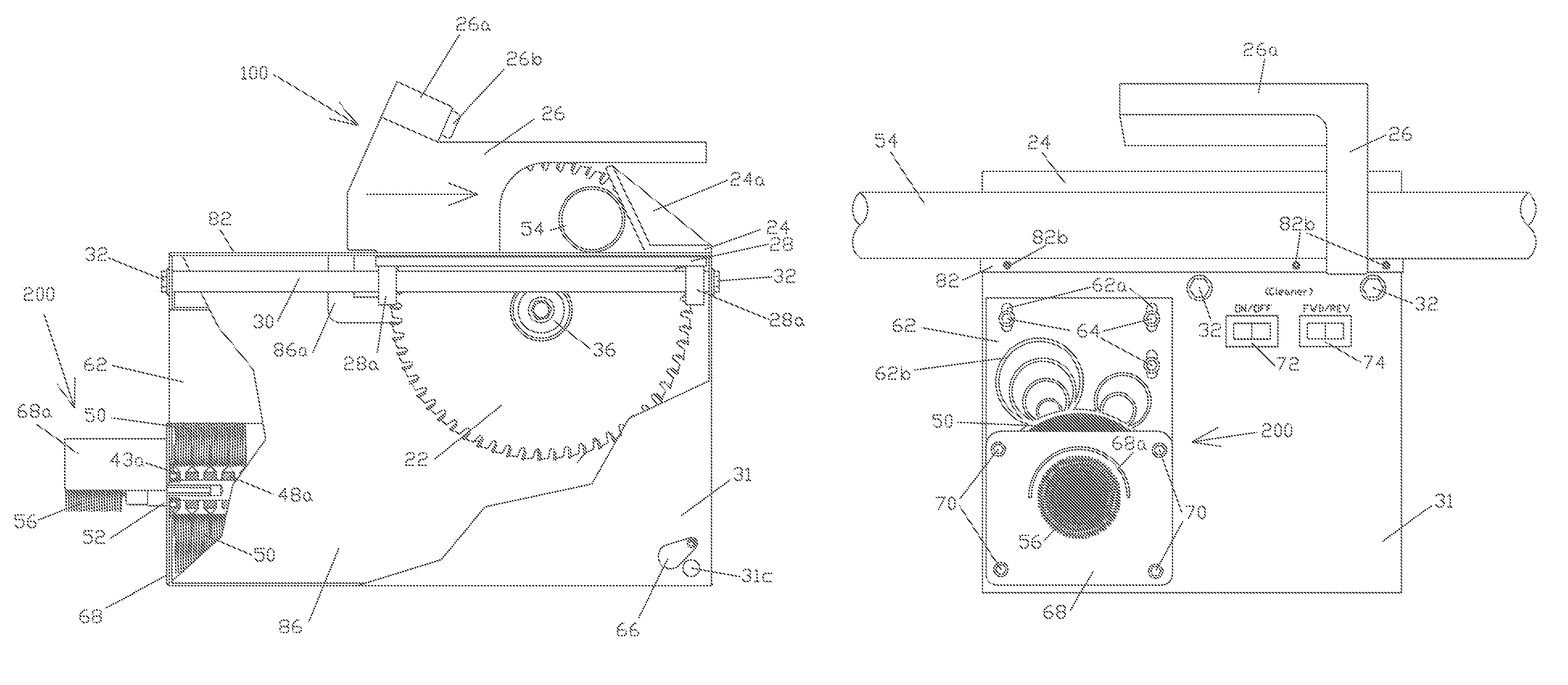
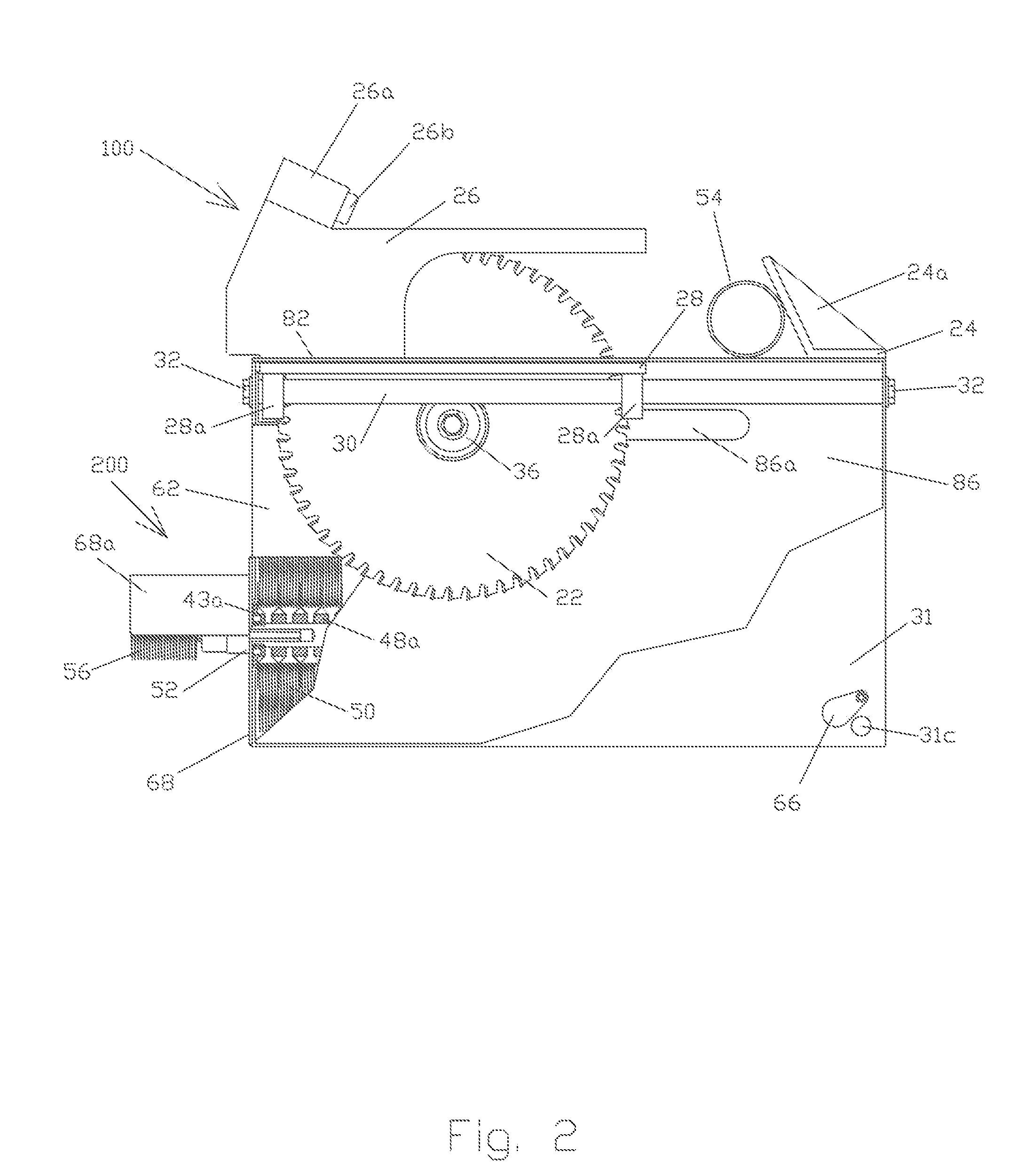
[0044]FIGS. 2, 3, 4 and 5 are, respectively, right and left side cut away views of an embodiment of the present invention showing the relative position of the components comprising the cutoff assembly 100 and the cleaner assembly 200.

[0045]Referring now to FIG. 2, the cutoff assembly 100 is comprised of a base plate 28 which is fabricated of metal, plastic or other suitable material, having a base plate relief 28b to accommodate a circular cutoff blade 22. Circular cutoff blade 22 has peripheral chamfer cutting teeth 23 which are fabricated of tungsten carbide or other suitable material for cutting ferrous, nonferrous and other materials.

[0046]A guide rail sleeve 28a which is fabricated of metal, plastic or other suitable material is affixed by weld or other suitable method to the underside of the base plate 28. The guide rail sleeve 28a is positioned on the underside of th...


PUM

PropertyMeasurementUnit
sizeaaaaaaaaaa
diameteraaaaaaaaaa
stressaaaaaaaaaa

Abstract

A tubing preparation machine is an electrically powered mechanical device housed in one convenient housing assembly. A cutoff assembly is provided that virtually eliminates the need for the reaming and deburring of the cut end of tubing and a cleaner assembly is provided that has a tubing alignment guide to accept tubing to the correct depth for cleaning while stabilizing the tubing during the cleaning process. A quick release chuck allows the operator to easily attach the correct size fitting cleaner brush. The tubing preparation machine is portable, lightweight and easily hand carried by use of a handle provided on the housing assembly cover. The tubing preparation machine provides for unparalleled, safe, convenient and efficient preparation of tubing and related fittings.

Description

RELATED APPLICATIONS[0001]The present application is a continuation application of U.S. provisional patent application Ser. No. 60 / 579,937, filed Jun. 15, 2004, by Francis Paul Fruzzetti Jr. and Robert James Frerking, included by reference herein and for which benefit of the priority date is hereby claimed.FIELD OF THE INVENTION[0002]The present invention relates to the cutting and cleaning of tubing and related fittings in the preparation for joining the components by soldering or other meansBACKGROUND OF THE INVENTION[0003]Tubing and related fittings have been used for piping systems over the years. The preparation and use of tubing and related fittings in any piping system requires that the cutting and subsequent cleaning of the tubing and related fittings be done in a manner to ensure proper assembly to industry standards. In the cutting of the tubing, in many instances, the method of cutting the tubing results in a need for the reaming of the interior of the cut edge of the tub...

Claims


Application Information

Patent Timeline
Patent Type & Authority Patents(United States)
IPC IPC(8): B08B9/02B23D21/00
CPCB08B1/04B08B9/021B08B9/023B23D45/061B23D45/12B23D47/00B23D47/04A46B13/001A46B13/02A46B15/0055
Inventor FRUZZETTI, JR., FRANCIS PAULFRERKING, ROBERT JAMES
Owner FRUZZETTI JR FRANCIS PAUL
Why Eureka
Try Eureka