Optical biosensor for biomolecular interaction analysis

a biomolecular interaction and optical technology, applied in the field of optical biosensors for biomolecular interaction analysis, can solve the problems of cost and improvement still demanded, and achieve the effect of reducing the size and cost of the measuring device and simplifying the device construction

Inactive Publication Date: 2010-07-13
HITACHI LTD
View PDF6 Cites 16 Cited by
  • Summary
  • Abstract
  • Description
  • Claims
  • Application Information

AI Technical Summary

Benefits of technology

[0007]In view of the above-mentioned problems with the related art, one object of the present invention is to enable biomolecular interactions to be analyzed by a small and simple device. Another object of the present invention is to enable biomolecular interactions to be analyzed at a lower cost.
[0013]According to the present invention, since a change of the intensity of the reflected light due to a shift of the absorption wavelength is measured by using the noble metal nanoparticles and the amount of the change is measured with attention focused on a particular wavelength within the measurement wavelength range, the measurement comparable to the case of using a spectrophotometer can be performed with a simpler device construction. Further, the measuring device can be reduced in size and cost.

Problems solved by technology

On the other hand, the biomolecule detecting method disclosed in Patent Document 1 has succeeded in realizing considerable simplification, but an improvement is still demanded in point of cost because it requires a relatively expensive device, such as a spectrophotometer.

Method used


Image

  • Optical biosensor for biomolecular interaction analysis
  • Optical biosensor for biomolecular interaction analysis
  • Optical biosensor for biomolecular interaction analysis

Examples


Embodiment Construction

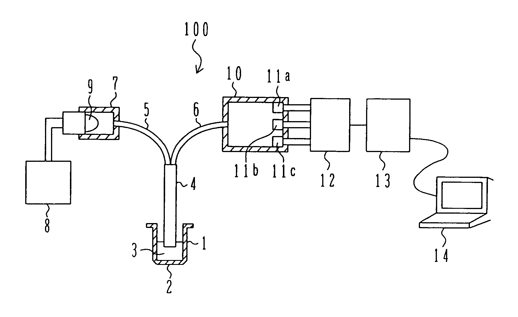
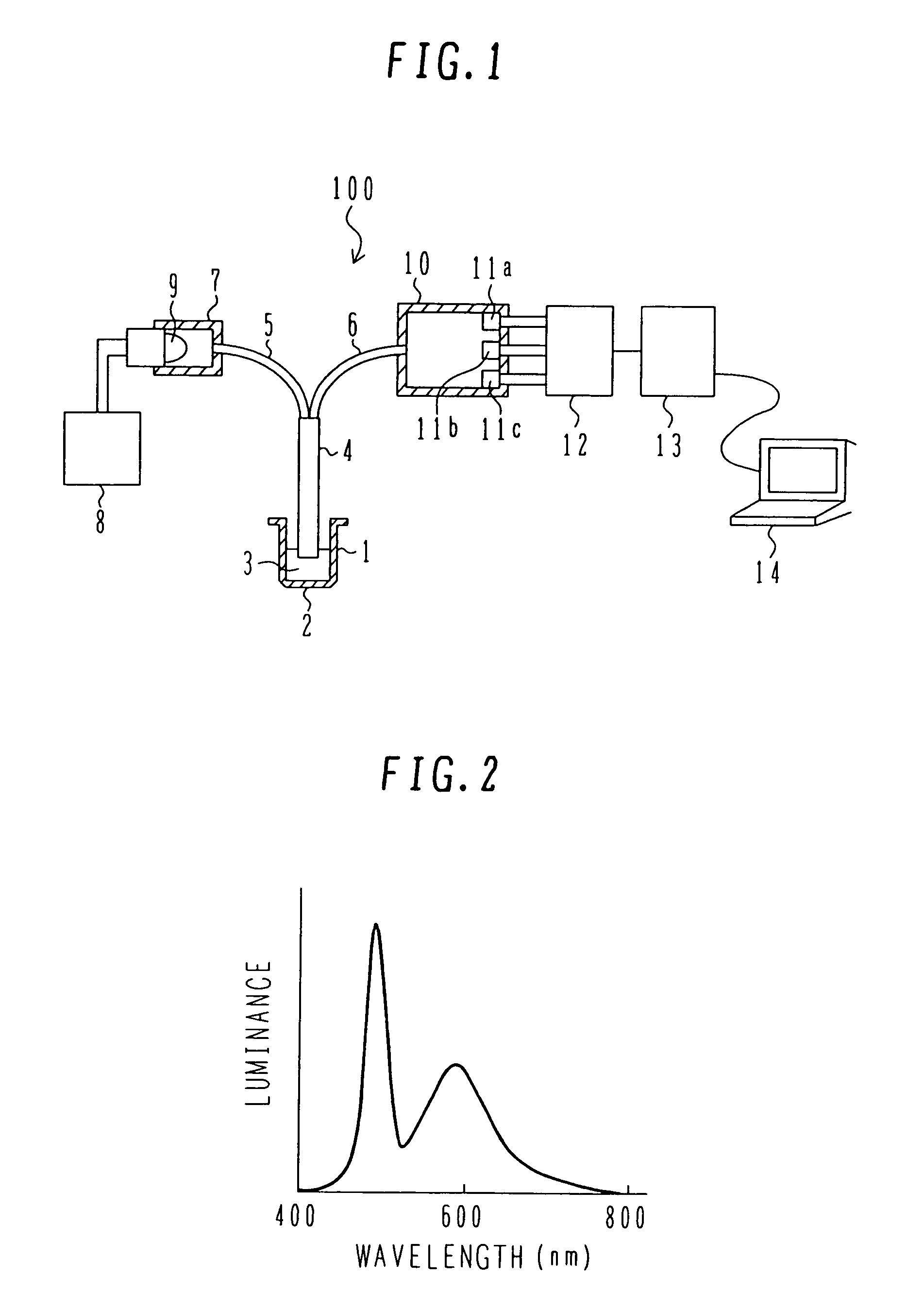
[0022]Measuring devices for biomolecular interaction analysis according to several embodiments of the present invention will be described below with reference to the drawings. FIG. 1 is a schematic view of a measuring device for biomolecular interaction analysis, i.e., a device 100 for measuring a biomolecular binding amount, according to one embodiment of the present invention. A sensor well 1 serving as a container for containing an analysis sample 3 to be measured is in the form similar to a sample plate usually used in biochemical analysis. A noble metal nanoparticle sensor 2 similar to that disclosed in the above-cited Patent Document 1 (JP,A 2000-55920) is formed at the bottom of the sensor well 1. The surface of the noble metal nanoparticle sensor 2 is chemically modified or includes an analyte material fixed to it, e.g., an antigen, depending on the analysis purpose. In this embodiment, a running buffer, e.g., a phosphate buffer solution, is used as the analysis sample 3.

[00...


PUM

PropertyMeasurementUnit
wavelength bandaaaaaaaaaa
particle sizeaaaaaaaaaa

Abstract

Biomolecular and other interactions are analyzed with a simpler construction. A biotic sample is fixed to noble metal nanoparticles, and light is irradiated from a light source to the noble metal nanoparticles through an optical fiber. Light obtained after reflection of the irradiated light by the noble metal nanoparticles is introduced to one or more optical detecting units through another optical fiber. The optical detecting unit(s) separately measure the intensity of the input light in a second band including a maximum absorption wavelength, a first band covering a longer wavelength range than the range covered by the second band, and a third band covering a shorter wavelength range than the range covered by the second band.

Description

BACKGROUND OF THE INVENTION[0001]1. Field of the Invention[0002]The present invention relates to an optical biosensor for biomolecular interaction analysis. More particularly, the present invention relates to a measuring device and method for biomolecular interaction analysis, which are suitable for use in medical diagnoses, food inspection, etc.[0003]2. Description of the Related Art[0004]The principle for analyzing biomolecular interactions is described in Non-Patent Document 1 (Kazuhiro Nagata and Hiroshi Handa, “Real Time Analysis Experimentation for Interactions between Biological Substances”, pp. 13-26, Springer Verlag Tokyo). In this document, to fabricate an immunity sensor or a gas sensor utilizing surface plasmon resonance (SPR), a compression wave of free electrons is excited to cause resonance at an interface between a metal thin film and a dielectric while propagating along the interface.[0005]Another example for analyzing biomolecular interactions is disclosed in Paten...

Claims


Application Information

Patent Timeline
Patent Type & Authority Patents(United States)
IPC IPC(8): G01N21/00G01N21/63G01N21/62G01N21/27G01N21/41G01N33/553
CPCG01N21/314G01N21/554G01N21/274G01N2021/258G01N2021/3148
Inventor MIYAMOTO, TETSUROHAKARI, MAMITOGASHI, SHIGENORI
Owner HITACHI LTD
Why Eureka
Try Eureka