Centrifugal fan with turbulence inducing inlet bell

a centrifugal fan and inlet bell technology, applied in the field of centrifugal fans, can solve problems such as cost increase, and achieve the effects of reducing noise, improving air intake, and increasing output efficiency

Active Publication Date: 2010-07-20
GREENHECK FAN
View PDF12 Cites 16 Cited by
  • Summary
  • Abstract
  • Description
  • Claims
  • Application Information

AI Technical Summary

Benefits of technology

[0012]The present invention provides a centrifugal fan having increased output efficiency and decreased noise resulting from improved distribution of intake air along a greater area of radial fan blades.
[0015]The wall of the inlet bell generally has a smooth contour following as straight line or large radii, while the arcuate surface of the turbulator has a much smaller radius. The relatively small radius contour of the turbulator provides the disruption of smooth laminar type flow over the large radius contours of the inlet bell to thereby induce turbulence in the air. The random flow of the turbulent air thus reduces of separation of the air from the large radius contours of the inlet bell downstream from the turbulator at the inlet bell / impeller interface so that the air will travel in the direction of curvature of the inlet bell. Thus, at least some of the air follows a path that turns at an angle of less than 90 degrees as it passes from the inlet bell to the impeller.
[0016]Thus, the centrifugal fan has an inlet bell that induces turbulence in the intake air stream so as to better distribute air across the rotating radial fan blades and thereby increase fan efficiency. The “turbulator” feature is one or more surfaces integrally formed in the inlet bell to either project into or away from the intake air stream. The turbulator disrupts smooth air flow across the inside surface of the inlet bell has the effect of randomizing the air at the boundary layer to reduce separation of the air from the inlet bell as it leaves the inlet bell and enters the impeller. The air can thus follow the contour of the inlet bell more closely to make a tighter radius turn as it enters the impeller. In so doing, air is delivered across more of the fan blades so that output air flow is increased.

Problems solved by technology

However, the complex fan blades designs, convex wheel back and partial cone shape of the wheel cone complicates the fan design and manufacturing, and thereby increases cost, by requiring the fan blades to be formed with complex three-dimensional surfaces.

Method used


Image

  • Centrifugal fan with turbulence inducing inlet bell
  • Centrifugal fan with turbulence inducing inlet bell
  • Centrifugal fan with turbulence inducing inlet bell

Examples


Embodiment Construction

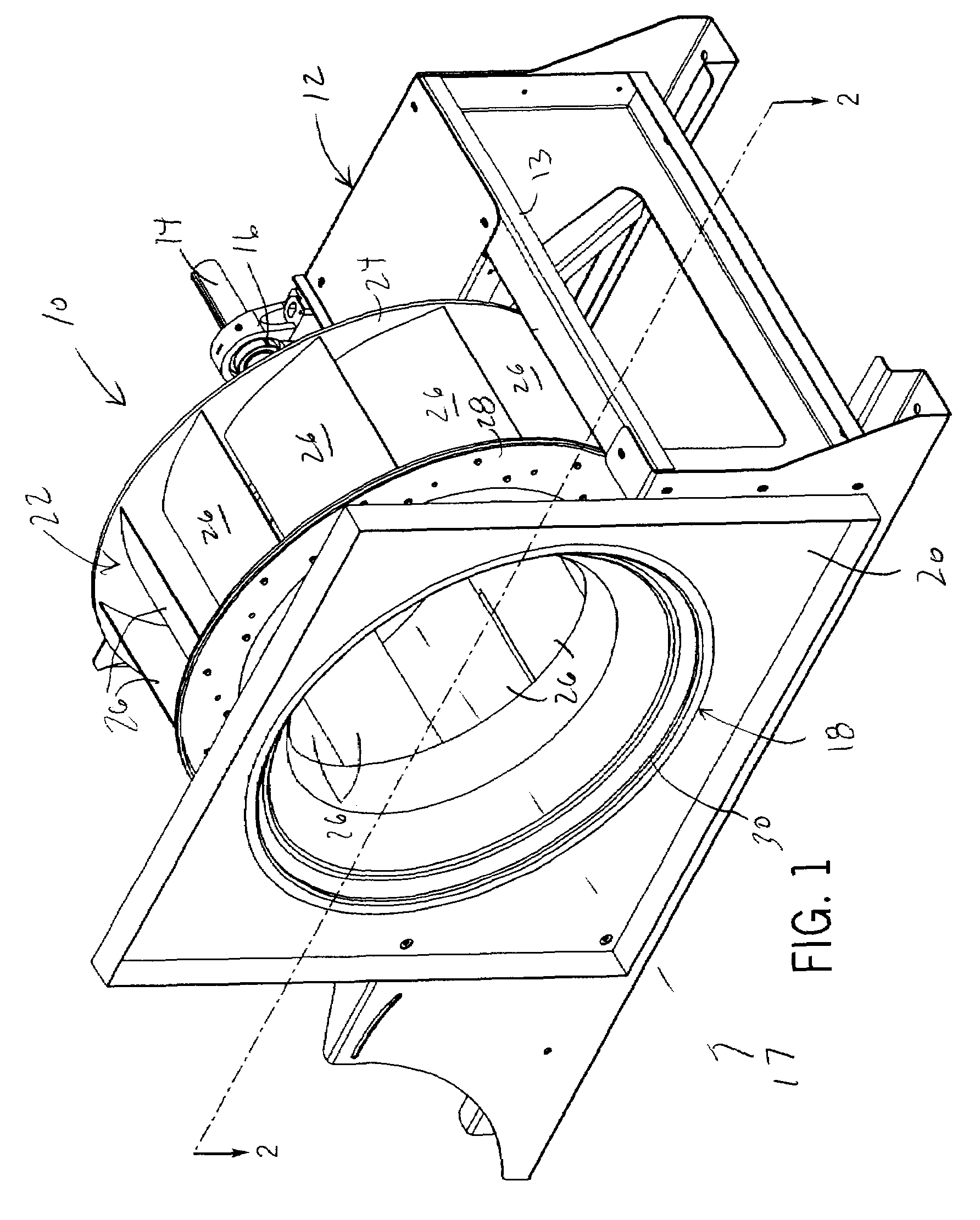
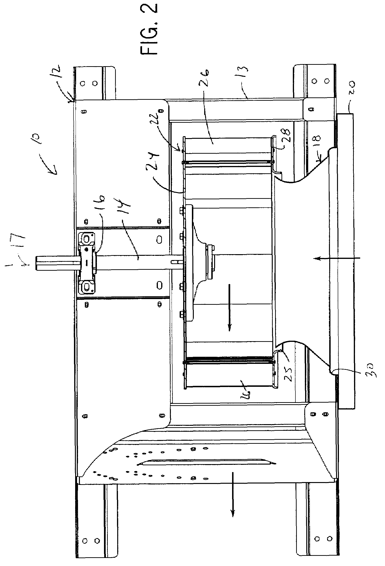
[0022]Referring initially to FIGS. 1 and 2, an in-line centrifugal fan 10, includes a wheel mount 12 having supporting framework 13 and a rotatable shaft 14 and bearing 16 assembly to which is coupled an electric motor (not shown) via a direct drive or drive pulley arrangement (not shown). The shaft 14 extends along a shaft axis 17. It should be appreciated that various motor sizes and drive combinations are available to produce fans capable of circulating air at various flow rates.

[0023]A fan constructed in accordance with the present invention achieves a reduced brake horsepower needed to achieve the same airflow compared to the prior art, thereby resulting in a significantly greater efficiency. Additionally, the present invention achieves a dramatic reduction in sound levels during operation at any given fan static pressure. The sound pressure emanating from a fan constructed in accordance with the present invention is significantly less than the sound pressure emanated from the ...


PUM


Abstract

A centrifugal fan has an inlet bell that induces turbulence in the intake air stream so as to better distribute air across the rotating radial fan blades and thereby increase fan efficiency. The “turbulator” feature is one or more preferably arcuate surfaces integrally formed in the inlet bell to either project into or away from the intake air stream. The turbulator disrupts smooth air flow across the inside surface of the inlet bell has the effect of randomizing the air at the boundary layer to reduce separation of the air from the inlet bell as it leaves the inlet bell and enters the impeller. The air can thus follow the contour of the inlet bell more closely to make a tighter radius turn as it enters the impeller. In so doing, air is delivered across more of the fan blades so that output air flow is increased.

Description

CROSS-REFERENCE TO RELATED APPLICATION[0001]Not applicable.STATEMENT OF FEDERALLY SPONSORED RESEARCH OR DEVELOPMENT[0002]Not applicable.BACKGROUND OF THE INVENTION[0003]1. Technical Field[0004]The present invention relates generally to an in-line centrifugal fan, and in particular, to a centrifugal fan having a high operating efficiency and reduced sound.[0005]2. Description of the Related Art[0006]High performance fans are used in variety of industrial and laboratory applications to rapidly evacuate a large volume of air into, out of or through a building. The performance and desirability of a fan is measured generally by the fan's efficiency and sound levels produced during operation. The optimization of these two components will reduce the energy needed to operate the fan and / or increase output flow, thus conserving cost, and will further reduce the noise pollution associated with operation.[0007]Fans are generally classified according to the direction of airflow through the impe...

Claims


Application Information

Patent Timeline
Patent Type & Authority Patents(United States)
IPC IPC(8): F04D29/44
CPCF04D29/162F04D29/4213F04D29/441F05D2250/51
Inventor KURSZEWSKI, SCOTT S.KUSKI, TIMOTHY
Owner GREENHECK FAN
Why Eureka
Try Eureka