Heating device and heating method

a heating device and heating method technology, applied in the field of heating devices for and heating methods, can solve the problems of obstructing the sublimate cannot be satisfactorily carried away from the space by the unidirectional air flow, and the difficulty of forming the heating device in a small thickness, so as to achieve the stabilization of the movement of the substrate, the reduction of the thickness of the heating device, and the effect of reducing the thickness of the heating

Inactive Publication Date: 2010-07-20
TOKYO ELECTRON LTD
View PDF15 Cites 4 Cited by
  • Summary
  • Abstract
  • Description
  • Claims
  • Application Information

AI Technical Summary

Benefits of technology

[0021]As mentioned above, the present invention floats the substrate above the cooling plate and the heating plate, carries the substrate longitudinally or horizontally into the flat heating chamber, and subjects the substrate to the heating process. Therefore, the heating chamber is not provided with a vertically movable cover and any operation for transferring the substrate to the heating plate is not necessary. Thus mechanisms for vertically moving the cover and for transferring the substrate to the heating plate, and a vertical space for the operation of the mechanisms are unnecessary, and the thickness of the heating device can be reduced accordingly.
[0022]The pushing mechanism for applying pushing force to the front or the back part of the substrate when the substrate is moved between the cooling plate and the heating plate applies pushing force to the back part of the substrate with respect to a direction in which the substrate is moved by the pushing member against pushing force exerted on the substrate by the flotation gas spouted through the flotation gas spouting ports or applies pushing force to the front part of the substrate with respect to the moving direction of the substrate by moving the pushing member in the direction in which the flotation gas is spouted. Thus pushing force of either the gas or the pushing mechanism is applied to the front and the rear end of the substrate when the substrate is moved. Therefore, the longitudinal displacement of the substrate in the moving direction can be prevented and the movement of the substrate can be stabilized.
[0023]The gas spouted through the centering gas spouting ports exerts pushing force so as to center the substrate with respect to the center line of the substrate moving passage. Thus the transverse displacement of the substrate during movement can be prevented and the movement of the substrate can be further stabilized.

Problems solved by technology

Consequently, it is difficult to form the heating device in a small thickness.
Consequently, the sublimates cannot be satisfactorily carried away from the space by the unidirectional air flow.
However, when the top plate 18 is supported vertically movably, a space for installing the lifting mechanism and a space in which the top plate 18 is moved vertically are necessary, which obstructs reducing the thickness of the heating device.
Since any frictional force acts on the floating substrate, the substrate is unstable and is moved by a slight force.
Therefore, the substrate is liable to drift longitudinally or transversely when the gas is spouted in the moving direction.
Consequently, this known structure has difficulty in stabilizing and stably moving a wafer and in stopping the wafer W at a desired position.
Thus this known structure is unpractical.

Method used


Image

  • Heating device and heating method
  • Heating device and heating method
  • Heating device and heating method

Examples


Embodiment Construction

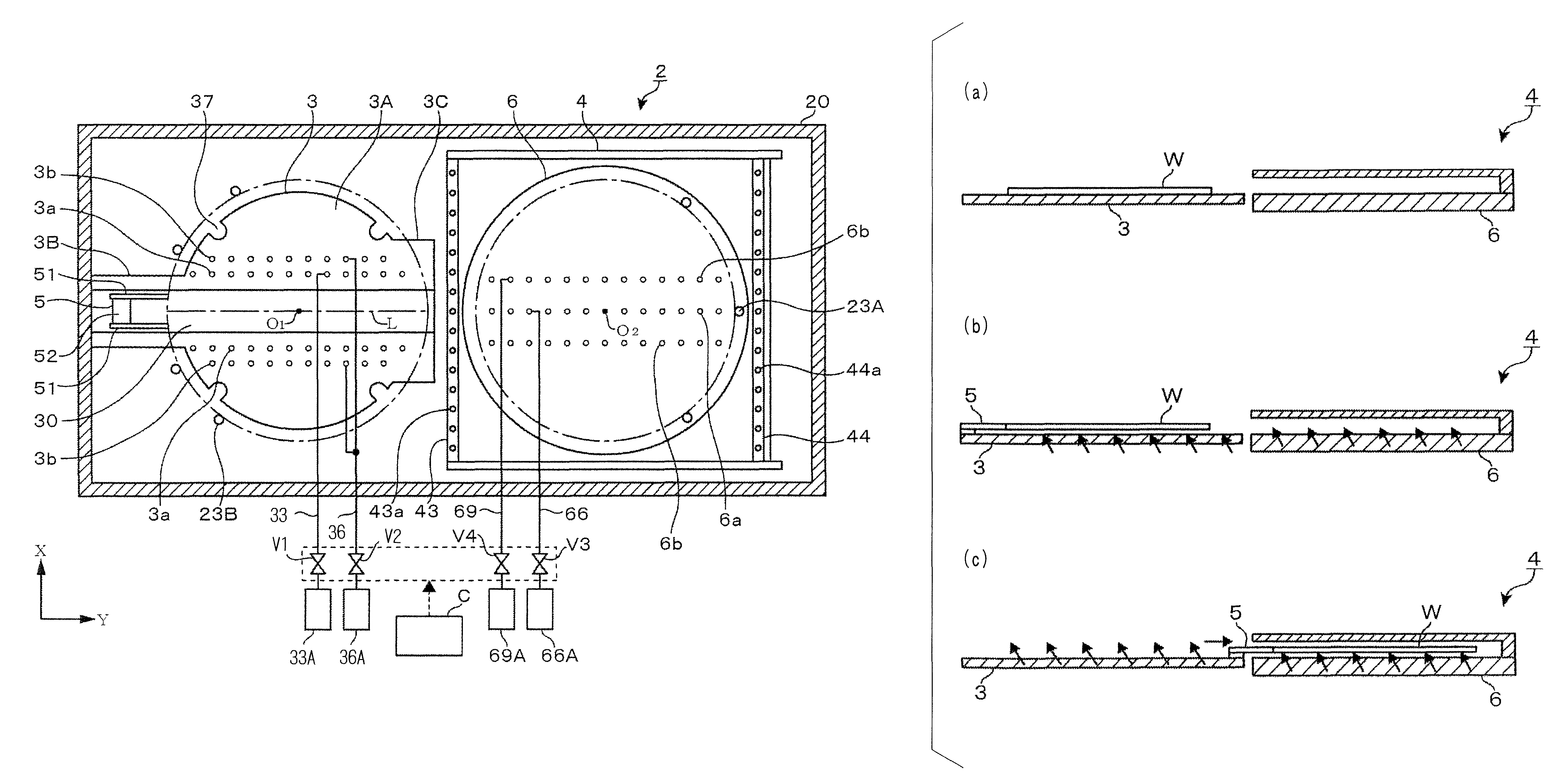
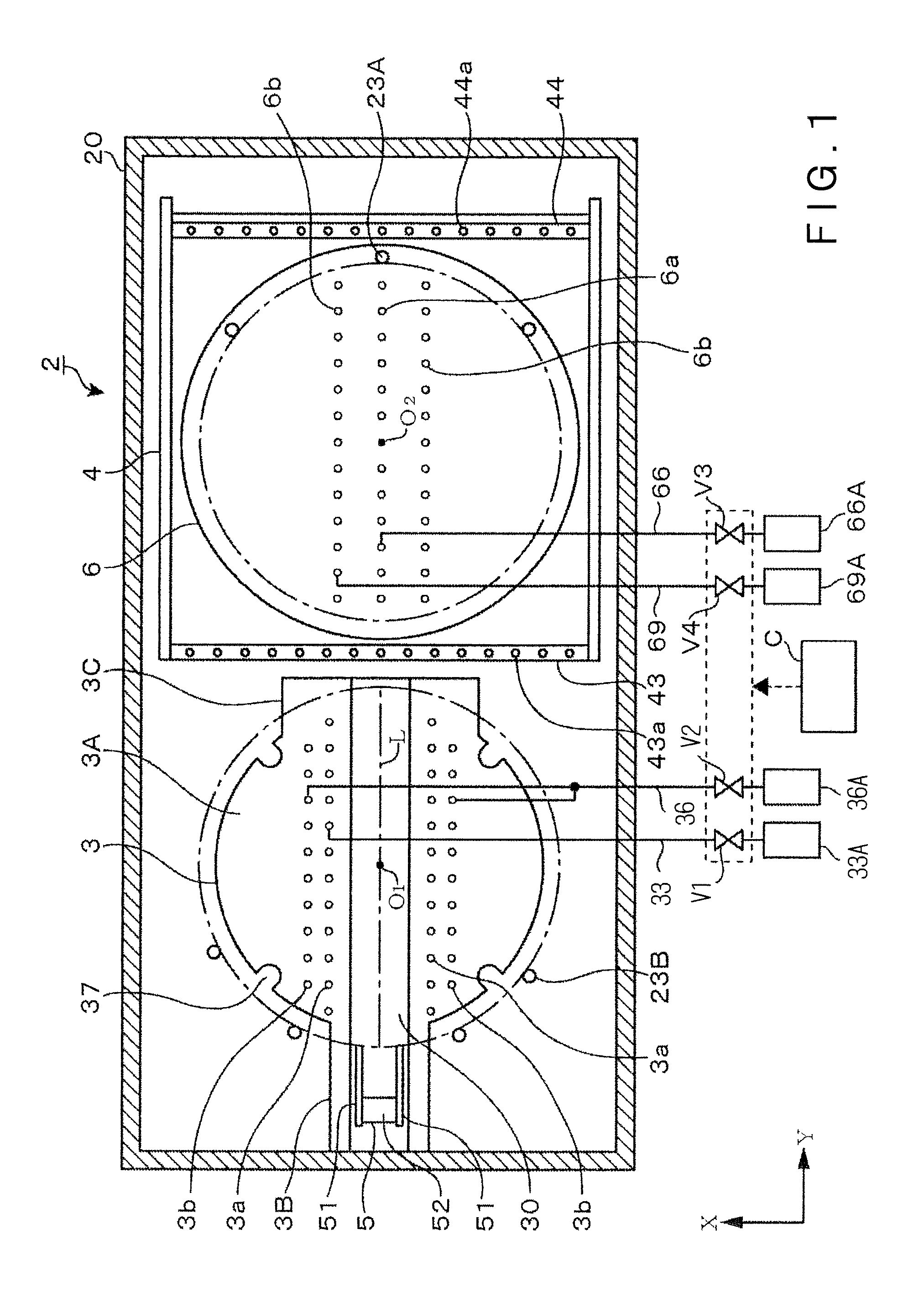
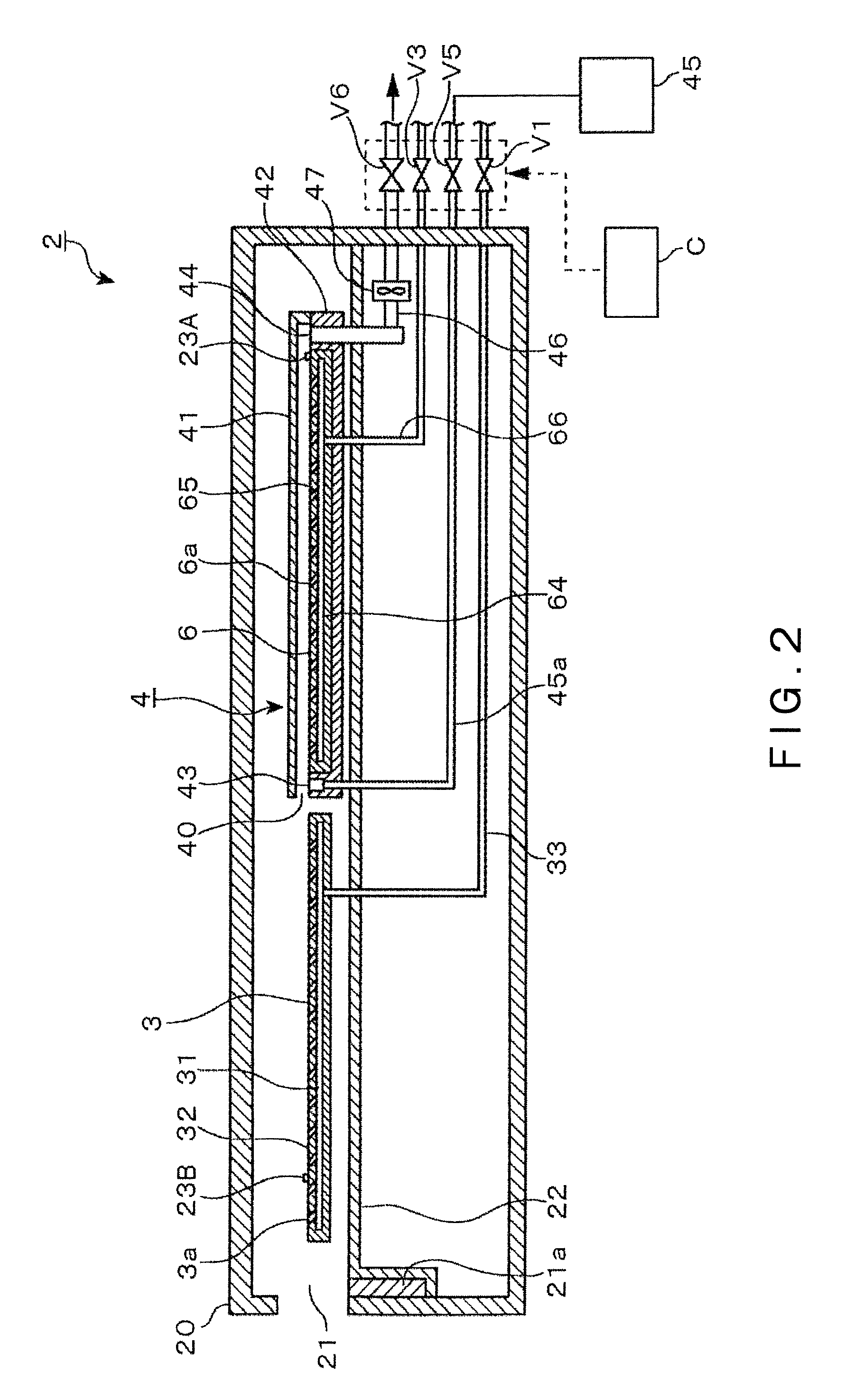
[0043]A heating device 2 in a preferred embodiment according to the present invention will be described with reference to the accompanying drawings as applied to forming a resist film on a surface of a wafer W, namely, a substrate, by processing the wafer coated with a liquid resist film by a heating process. The wafer W is, for example, a 12 in. wafer. Referring to FIGS. 1 and 2, the drying device 2 has a box 20 serving as a processing vessel. The box 20 has an end wall provided with an opening 21 through which the wafer W is carried into and carried out of the box 20. The opening21 is covered with a shutter 21a. The shutter 21a prevents the disturbance of air flows around the wafer W by external air flowed through the opening 21 into the box 20 while the wafer W is being heated. An air curtain may be formed near the opening 21 instead of disposing the shutter near the opening 21 to exclude external air.

[0044]A base 22 is disposed in a lower part of the interior of the box 20. A si...


PUM

PropertyMeasurementUnit
thicknessaaaaaaaaaa
thicknessaaaaaaaaaa
thicknessaaaaaaaaaa

Abstract

A heating device provided with a cooling plate and a heating plate is formed in a low height, and floats a substrate above the cooling plate and the heating plate and moves the substrate horizontally between the cooling plate and the heating plate by the pressure of a gas. A heating device 2 includes a cooling plate 3 provided with flotation gas spouting ports 3a, and a heating plate provided with flotation gas spouting ports. The flotation gas spouting ports 3a and 3b are arranged along a wafer moving passage and are formed so as to spout the gas obliquely upward toward a first end of the wafer moving passage on the side of the cooling plate. A pushing member 51 is brought into contact with a back part of a wafer W with respect to a direction in which the wafer W is moved to move the wafer W in a direction toward the heating plate 6 opposite a direction in which the flotation gas is spouted. The pushing member 51 is brought into contact with a back part of a wafer W with respect to a direction in which the wafer W is moved to move the wafer W in a direction toward the cooling plate 3 in which the flotation gas is spouted.

Description

BACKGROUND OF THE INVENTION[0001]1. Field of the Invention[0002]The present invention relates to a heating device for and a heating method of processing a substrate coated with a coating liquid by a heating process.[0003]2. Description of the Related Art[0004]A coating and developing system, which applies a resist to a semiconductor wafer (hereinafter, referred to as “wafer”) and processes the wafer processed by an exposure process by a developing process, is used as a resist pattern forming system for forming a resist pattern on a wafer or a glass substrate for a LCD (liquid crystal display). The coating and developing system includes a heating device called a baking device. A heating device for heating, for example, a wafer coated with a liquid resist film dries the liquid resist film by removing a solvent contained in the liquid resist film.[0005]The inventors of the present invention are making an effort to use a heating device, which covers a space extending over a heating plat...

Claims


Application Information

Patent Timeline
Patent Type & Authority Patents(United States)
IPC IPC(8): F27D3/00
CPCF27B5/04F27B17/0025F27D5/0037F27D15/02H01L21/67109H01L21/67748H01L21/67784Y10S414/139G03F7/168
Inventor AKIMOTO, MASAMIHAYASHI, SHINICHIIIDA, NARUAKIINADOMI, HIROAKI
Owner TOKYO ELECTRON LTD
Why Eureka
Try Eureka