
Mass spectrometer

Active Publication Date: 2010-07-20
THERMO FINNIGAN
View PDF12 Cites 27 Cited by
  • Summary
  • Abstract
  • Description
  • Claims
  • Application Information

AI Technical Summary

Benefits of technology

[0011]The objective of this invention is to avoid limitations of the above mass spectrometers by 1) physically separating ion paths through the mass spectrometer followed by ions to be fragmented and ions not to be fragmented, as well as by 2) using a common unit for subsequent pulsed injection of fragmented or non-fragmented ions into an accurate-mass analyser.
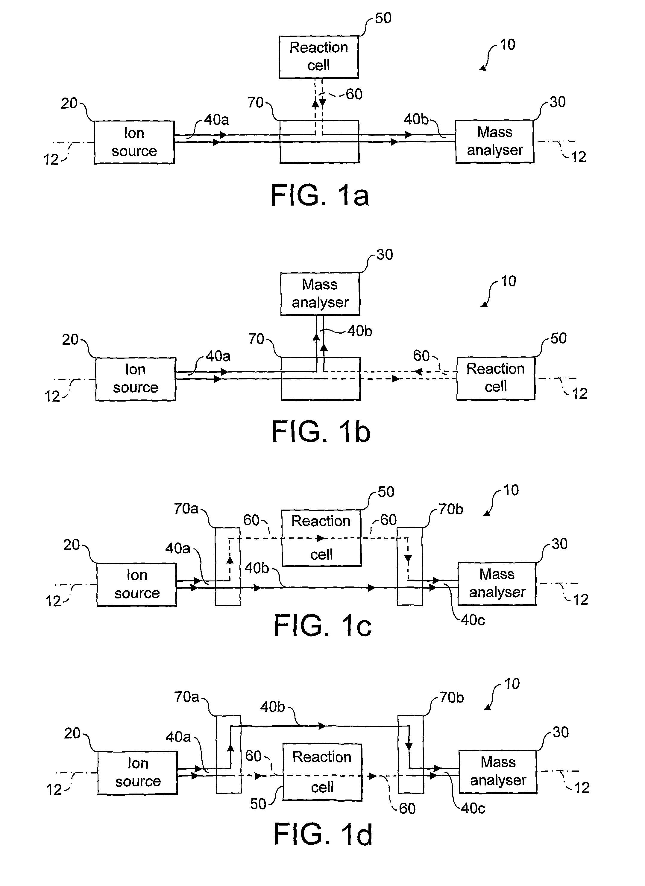
[0013]Locating the reaction cell on a branch ion path, as opposed to the main ion path to the analyser, means that the reaction cell may be bypassed when a mass spectrum is to be collected from precursor ions. As a result, the reaction cell need not be switched on and off repeatedly: the reaction cell may be switched on at all times and the ion optics at the junction merely switched between guiding the ions to the reaction cell or direct to the mass analyser as pulses of ions. Generally, the speed of switching the ion optics will be more rapid than the speed of switching the reaction cell on and off (especially when reaction gases or hot cathode are present). For gas-filled cells, there is also a saving in ion transit times (typically a few to a few tens of milliseconds).
[0032]Advantageously, this allows the reaction cell to be operated continuously during operation of the mass spectrometer. Put another way, a method is provided for operating a mass spectrometer to collect mass spectra from precursor and product ions, wherein a reaction cell is left in an operational mode such that ions entering the reaction cell are processed to form product ions, and a change from obtaining mass spectra from precursor ions to product ions is effected by switching the ion path between a branch ion path to the reaction cell and a main ion path that bypasses the reaction cell.
[0034]For analysis of complex mixtures, the mass spectrometer could be used in two steps. In the first step of experiments, no mass selection is performed and all precursor ions and fragments of those precursor ions are measured by the mass analyser. These two mass spectra are compared to identify whether any said product ions correspond to any precursor ions, either by m / z or by difference of m / z. For reliable identification, m / z or difference of m / z should be determined with accuracy better than a) 0.01%; b) 0.002%; c) 0.001%; d) 0.0005%; e) 0.0002%, with increasing mass accuracy reducing chances of false positives.

Problems solved by technology

At best, this introduces a time delay and ion losses; at worst (e.g. for reactions with reactive gas), such switching is impossible on the time scale of analysis.
However, further stages of fragmentation may be performed such that the fragment ions may themselves be fragmented.
In CID, this necessitates evacuating the collision gas from the fragmentation cell which is a time-consuming process.
However, the continuous ion beam that exits the reaction cell in U.S. Pat. No. 6,586,727 is sampled by an orthogonal acceleration TOF analyser with quite low transmission and duty cycle, so sensitivity of the method gets compromised.
Generally linear geometry of such instruments makes installation of such novel methods quite difficult and prone to compromising analytical performance.
Although this geometry offers greater flexibility in the design and operation of the reaction cell, its utility is limited because of high ion losses caused by the low duty cycle of orthogonal pulsing.
The above mass spectrometers suffer from a number of problems, in addition to the problem of switching between fragmenting / non-fragmenting modes already described.
Consequently, the fragment spectra become very crowded and this limits the number of precursor / fragment pairs that will be found.
In addition, this also adversely affects the dynamic range of ion intensities that may be addressed in the search (i.e. low-intensity precursor peaks might go unnoticed).

Method used


Image

  • Mass spectrometer
  • Mass spectrometer
  • Mass spectrometer

Examples


Embodiment Construction

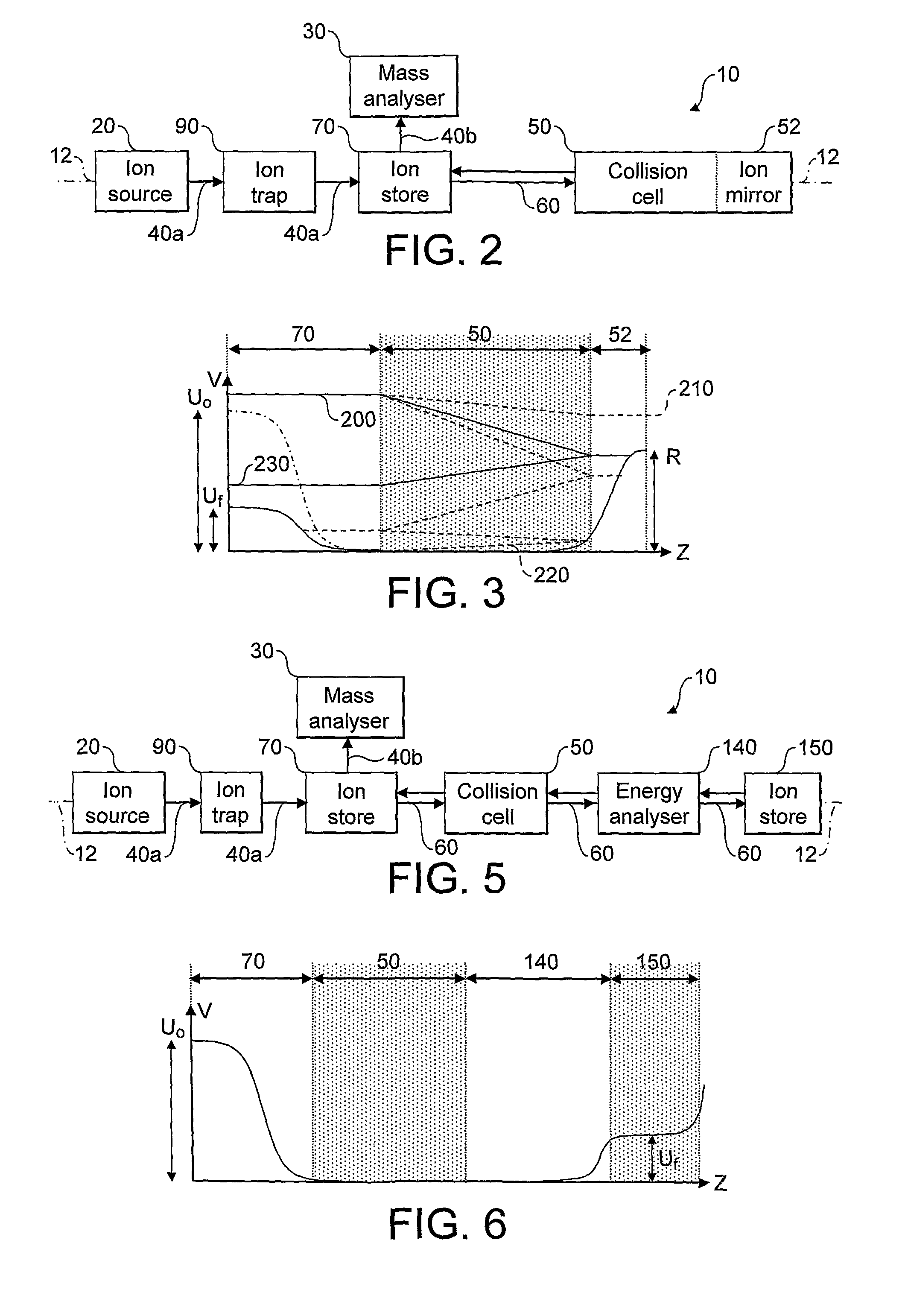
[0045]The present invention provides a mass spectrometer having a reaction cell and mass analyser provided on separate ion paths. This arrangement may be realised in several ways, and FIG. 1 shows four of the possible configurations in highly schematic form.

[0046]FIG. 1a shows an arrangement of a mass spectrometer 10 comprising an ion source 20, a mass analyser 30 located on a main ion path 40 and a reaction cell 50 located on a branch ion path 60. In FIGS. 1a to 1d, the main ion path is shown as the solid line 40, while the branch ion path is show as the broken line 60. The mass spectrometer 10 has a longitudinal axis 12 that coincides with the main ion path 40 extending from the ion source 20 to the mass analyser 30. The main ion path 40 has a first leg 40a that extends from the ion source 20 to a junction 70 formed by ion optics. A second leg 40b of the main ion path 40 continues from the junction 70 to the mass analyser 30. The branch ion path 60 extends from the junction 70 to ...


PUM


Abstract

This invention relates to mass spectrometers comprising a reaction cell and where mass spectra are collected both from unreacted ions and also from reaction product ions. In particular, although not exclusively, this invention finds use in tandem mass spectrometry where mass spectra are collected from precursor and fragment ions. The present invention provides an arrangement where ions may be sent to a reaction cell for fragmentation or other processing before onward transport to a mass analyser. Alternatively, ions may be passed directly to a mass analyser along a bypass path.

Description

FIELD OF THE INVENTION[0001]This invention relates to mass spectrometers comprising a reaction cell and where mass spectra are collected both from unreacted ions and also from reaction product ions. In particular, although not exclusively, this invention finds use in tandem mass spectrometry where mass spectra are collected from precursor and fragment ions.BACKGROUND OF THE INVENTION[0002]Mass spectrometers typically comprise an ion source where an analyte is ionised and extracted to pass to a mass analyser. Ion optics controls the passage of ions through the mass spectrometer. The ion path between ion source and mass analyser may include one or more ion traps / ion stores, and may also include a further mass analyser. Such a further mass analyser is often used for the rapid acquisition of pre-scans (i.e. low resolution mass spectra used for initial identification of ions). The other mass analyser tends to be of a higher resolution.[0003]In its broadest sense, this invention relates t...

Claims


Application Information

Patent Timeline
IPC IPC(8): H01J49/40H01J49/04
CPCH01J49/004H01J49/04
Inventor MAKAROV, ALEXANDER ALEKSEEVICH
Owner THERMO FINNIGAN
Learn More