Fast moving drilling rig

a drilling rig and fast technology, applied in the direction of drilling rods, drilling pipes, rotary drilling, etc., can solve the problems of large rigs, difficult to connect the center drill floor section, and assemble the drilling rig components on site, so as to reduce the time and reduce the time. the time required to transport the rig, the effect of convenient connection

Active Publication Date: 2010-08-03
NAT OILWELL DHT
View PDF39 Cites 63 Cited by
  • Summary
  • Abstract
  • Description
  • Claims
  • Application Information

AI Technical Summary

Benefits of technology

[0014]A method and apparatus for transporting and assembling a drilling rig is disclosed. The drilling rig of a preferred embodiment of the present invention utilizes specialized positioning pads integral to the side boxes of the drilling rig to facilitate the connection of the center drill floor section of the drilling rig to the side boxes of the rig. A preferred embodiment of the present invention may also utilize a specialized positioning dolly and an adjustable fifth-wheel truck connection for transporting the mast to the drill site, assembling the mast sections together, and positioning the mast for connection to the drill floor of the rig. The result is a unique drilling rig design and sequence for assembly that significantly reduces the time required to transport the rig from location to location and to assemble the rig at the drilling site.
[0015]In an alternative embodiment of the present invention, a standard drilling rig substructure without integral positioning pad...

Problems solved by technology

Typically, these drilling rigs are very large and, thus, must be transported to the drilling site in several pieces.
Assembling the drilling rig components on site, however, has proven to be a relatively complex and time-consuming process.
Additionally, after assembling the various pieces of the drill floor and the substructure, these large and extremely heavy sections of the drilling rig must be moved into position and aligned for connection.
Aligning the pin holes of these large sections of drilling rig is a difficult and time consuming process that typically requires the use of a crane.
This process can be extremely difficult if the area upon which the base side boxes rest is not well prepared such that it provides a fairly uniform and level “pad” for the drilling rig to rest on.
Given the fact that the equipment floor and the substructure typically require in excess of twenty (20) pins to connect them together, the process of aligning the pin holes and pinning these components together takes a significant amount of time.
Moreover, the process of pinning these components together can be dangerous for the rig personnel performing such task.
Once the substructure of the drilling rig—consisting of the side boxes, the elevating frames, and the...

Method used


Image

  • Fast moving drilling rig
  • Fast moving drilling rig
  • Fast moving drilling rig

Examples


Embodiment Construction

[0045]The following examples are included to demonstrate preferred embodiments of the invention. It should be appreciated by those of skill in the art that the techniques disclosed in the examples which follow represent techniques discovered by the inventor to function well in the practice of the invention, and thus can be considered to constitute preferred modes for its practice. However, those of skill in the art should, in light of the present disclosure, appreciate that many changes can be made in the specific embodiments which are disclosed and still obtain a like or similar result without departing from the spirit and scope of the invention.

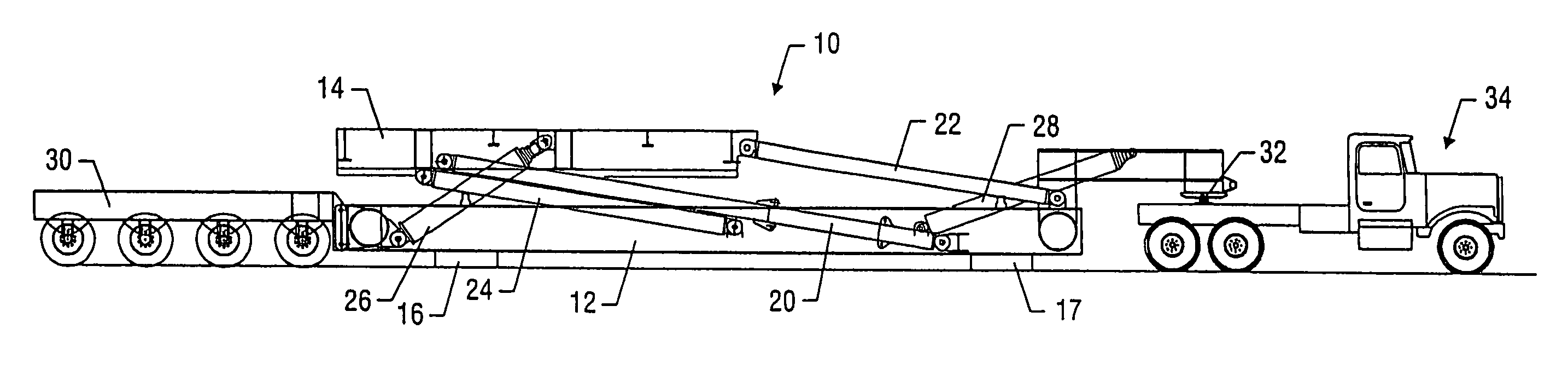
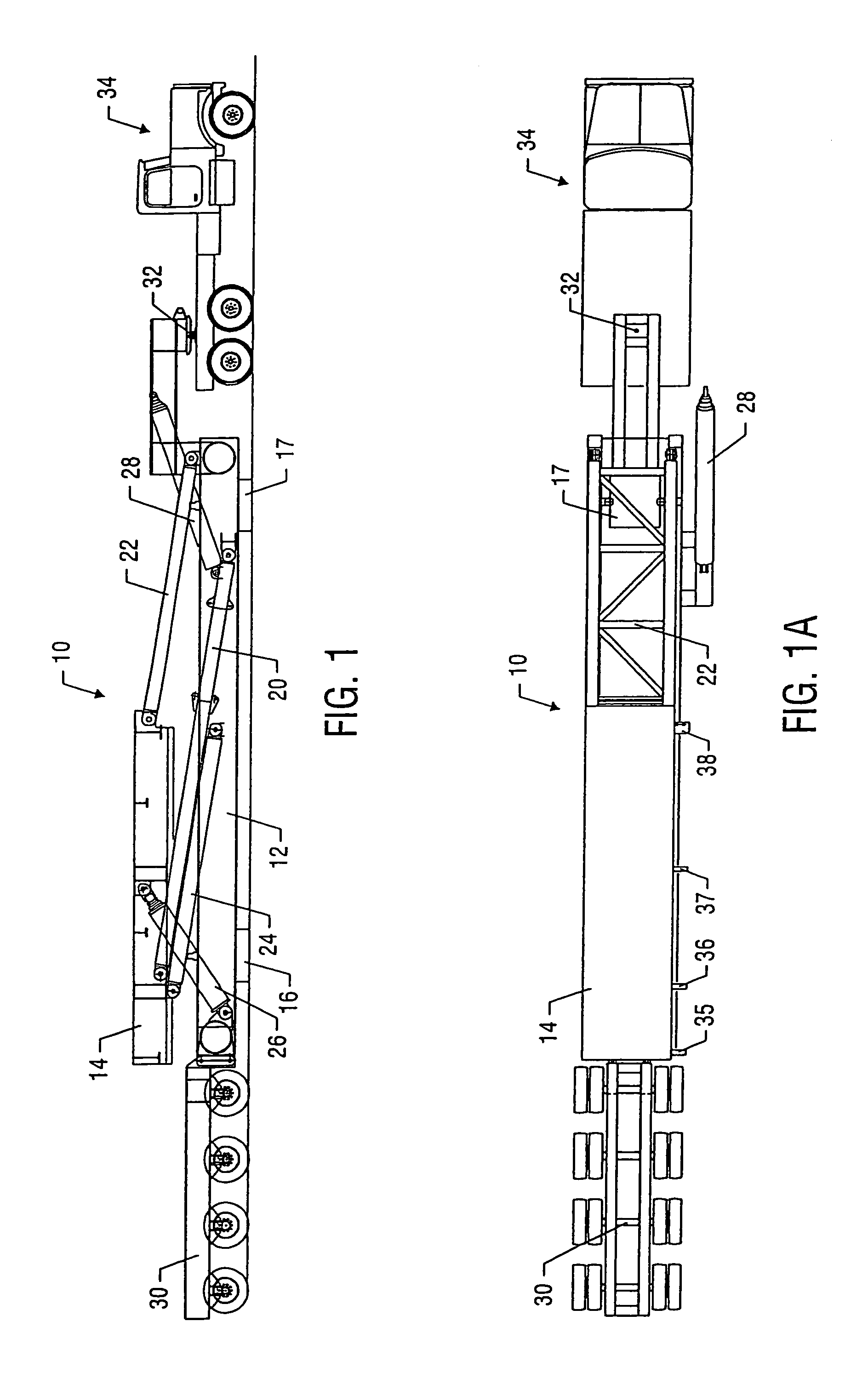
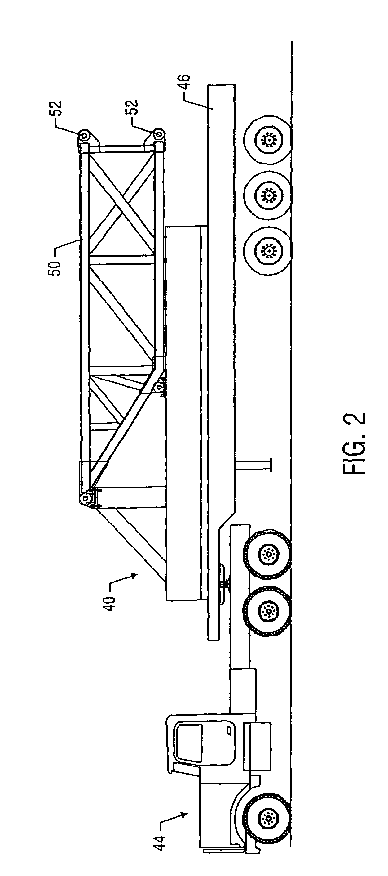
[0046]The unique features of the drilling rig design of the present invention will be understood by reference to the assembly of the rig as disclosed in the following paragraphs. References to like numerals in different figures are intended, as the various components shown in the figures appear in multiple figures. Further, references in th...


PUM


Abstract

A method and apparatus for transporting and assembling a drilling rig is disclosed. The drilling rig of a preferred embodiment of the present invention utilizes specialized positioning pads integral to the side boxes of the drilling rig to facilitate the connection of the center drill floor of the drilling rig to the side boxes of the rig. A preferred embodiment of the present invention may also utilize a specialized positioning dolly and an adjustable fifth-wheel truck connection for transporting the mast to the drill site, assembling the mast sections together, and positioning the mast for connection to the drill floor of the rig. The result is a unique drilling rig design and sequence for assembly that significantly reduces the time required to transport the rig from location to location and to assemble the rig at the drill site.

Description

[0001]This application claims the benefit of U.S. Provisional Application No. 60 / 466,029, filed Apr. 25, 2003.FIELD OF THE INVENTION[0002]The present invention relates to a transportable drilling rig particularly useful in the oil and gas industry. In particular, the invention relates to an improved drilling rig design that allows the drilling rig to be transported from location to location and assembled for operation in substantially less time than prior art drilling rigs.BACKGROUND OF THE INVENTION[0003]In most land-based drilling operations, such as when drilling for oil and gas on land, it is necessary to transport a drilling rig to the site where the drilling operations will take place. Typically, these drilling rigs are very large and, thus, must be transported to the drilling site in several pieces. These rigs are typically transported in pieces that comprise the three main sections of a drilling rig: the substructure, the equipment floor (or drill floor), and the mast. Depen...

Claims


Application Information

Patent Timeline
IPC IPC(8): E21B7/00E21B7/02E21B15/00
CPCE21B15/00E21B7/02
Inventor PALIDIS, ANASTASIOS
Owner NAT OILWELL DHT
Why Eureka
Try Eureka