Automatic transmission

a transmission and automatic technology, applied in mechanical actuators, mechanical apparatus, gearing, etc., can solve the problems of increasing increasing the total length of the oil passage, and difficulty in achieving uniform hydraulic control accuracy, so as to reduce the number of production steps and simplify the structure

Active Publication Date: 2010-08-03
HONDA MOTOR CO LTD
View PDF21 Cites 18 Cited by
  • Summary
  • Abstract
  • Description
  • Claims
  • Application Information

AI Technical Summary

Benefits of technology

[0007]An object of the present invention is to solve the aforementioned problems associated with the background art technology and to provide an automatic transmission which includes an oil passage with a simple structure provided for the twin clutches and allows the number of production steps to be reduced.
[0011]According to first and second aspects of the present invention, the first and second clutches are disposed on the same main shaft, so that oil pressure for controlling the twin clutches can be supplied from one end of the main shaft. Accordingly, the source of oil pressure can be concentrated on the one end, and oil passages to supply the oil pressure can be formed into a simple shape with a short total length. Moreover, it is possible to easily make the two oil passages the same length and thus easily achieve uniform response in hydraulic control. Furthermore, constituting the first and second clutches with the same components can reduce the number of production steps.
[0012]According to a third aspect of the present invention, it can be configured so that the connection / disconnection state of the rotational driving force can be switched alternately by the two clutches between adjacent gear ratios. It is therefore possible to obtain an automatic transmission capable of performing a quick gear shift operation with less gear shift shock.

Problems solved by technology

This leads to a problem of increasing the number of production steps.
Moreover, there were problems such that the total length of the oil passage is increased and a difference between distances from a hydraulic pressure source to the first and second clutches makes it difficult to attain uniform accuracy of hydraulic control.

Method used


Image

  • Automatic transmission
  • Automatic transmission
  • Automatic transmission

Examples


Embodiment Construction

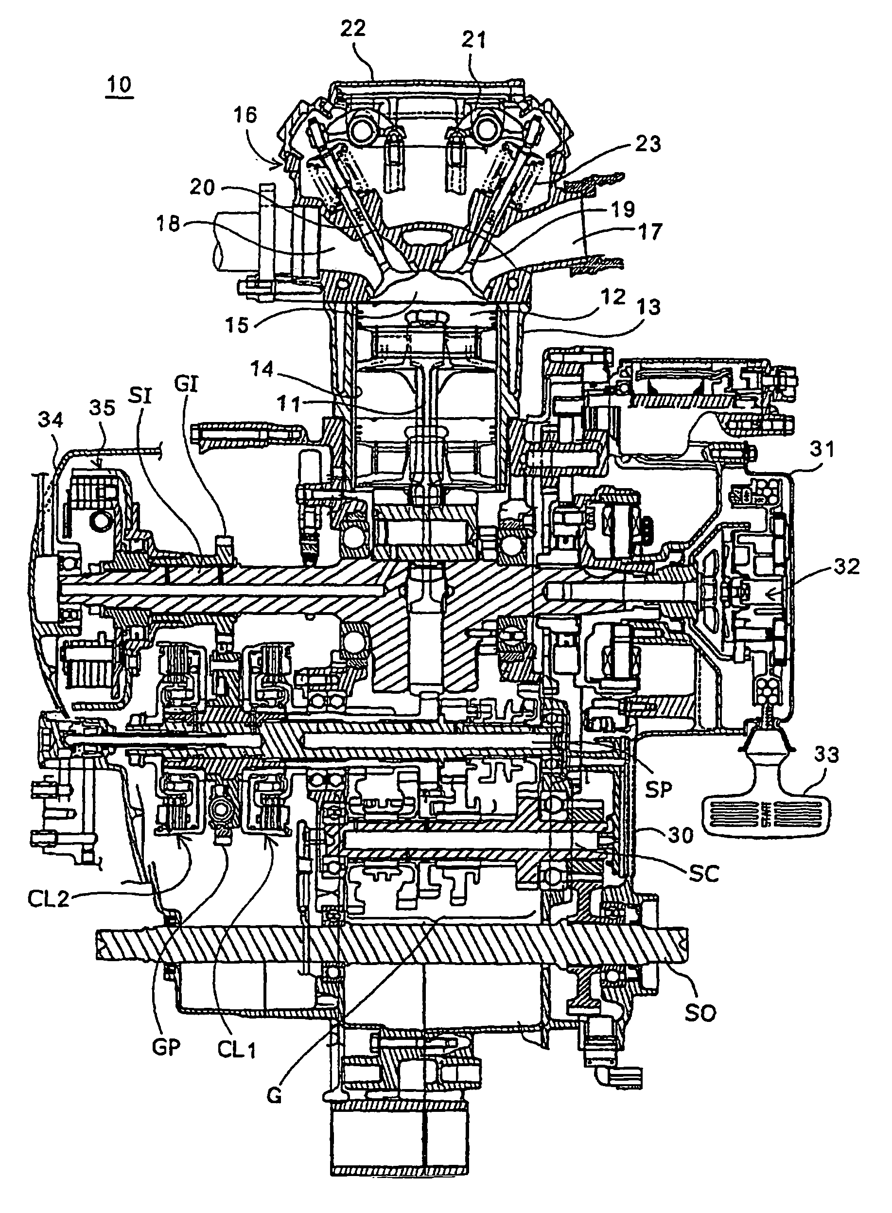
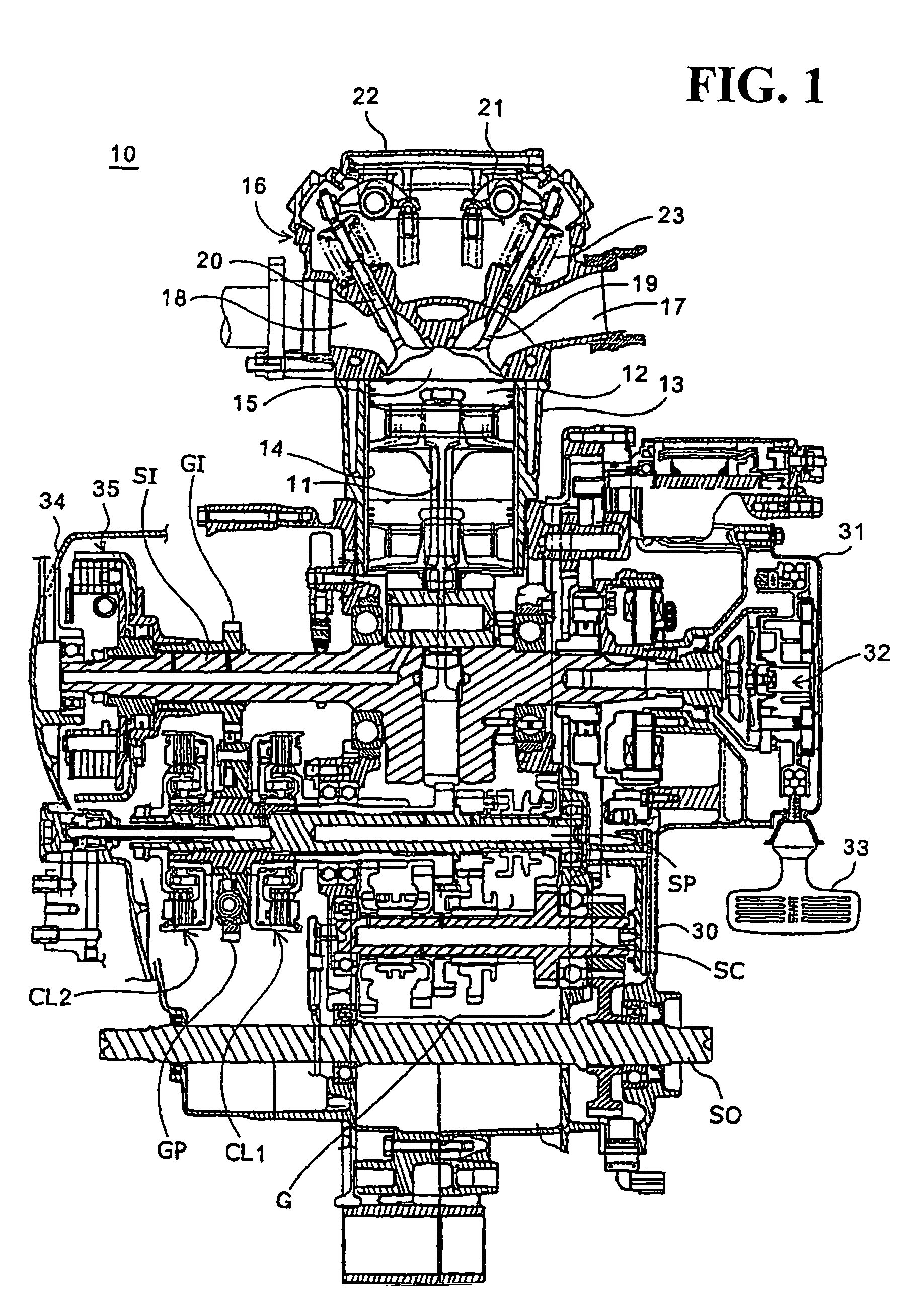
[0019]The present invention will now be described with reference to the accompanying drawings, wherein the same or similar elements will be identified with the same reference numerals. FIG. 1 is a cross-sectional view of an internal combustion engine to which an automatic transmission of an embodiment of the present invention is applied. An internal combustion engine 10 is a four cycle single cylinder engine and is mounted on, for example, a four-wheel all terrain vehicle (a saddle type vehicle for rough terrain). A crank shaft SI, which is rotatably supported about an axis thereof by a crankcase 30, is provided with a piston 12, which is connected thereto with a connecting rod 11 interposed therebetween. The piston 12 is slidable within a cylinder 14 provided in a cylinder block 13, and a cylinder head 16 is fixed to an upper part (in the drawing) of the cylinder block 13. The cylinder head 16, cylinder 14, and piston 12 define a combustion chamber 15 for combustion of a gas mixtur...


PUM


Abstract

An automatic transmission that includes oil passages with a simple structure provided for twin clutches can allow the number of production steps to be reduced. The automatic transmission includes a number of gear trains equal to the number of speeds between a primary shaft and a countershaft. The automatic transmission performs connection and disconnection of a rotational driving force between a crankshaft and a gearbox by means of twin hydraulic clutches including first and second clutches, which are made of the same components and disposed on the axis of the primary shaft back to back. Oil passages can be formed into a more simple shape and can be configured to have the same total length. The first clutch performs connection and disconnection for first and third speeds, and the second clutch performs connection and disconnection for second and fourth speeds.

Description

CROSS-REFERENCE TO RELATED APPLICATIONS[0001]This nonprovisional application claims priority under 35 U.S.C. §119(a) on Patent Application No. 2005-101035, filed in Japan on Mar. 31, 2005, the entirety of which is incorporated herein by reference.BACKGROUND OF THE INVENTION[0002]1. Field of the Invention[0003]The present invention relates to an automatic transmission. In particular, the present invention relates to an automatic transmission including twin clutches hydraulically driven and controlled.[0004]2. Description of Background Art[0005]An automatic transmission mounted on an internal combustion engine, that includes twin clutches is known in the background art. This automatic transmission includes two clutches (first and second clutches) between a crankshaft and a gearbox. The automatic transmission is capable of sequentially shifting gears without stopping a driving force by alternately connecting and disconnecting the first and second clutches in parallel to an automatic ge...

Claims


Application Information

Patent Timeline
Patent Type & Authority Patents(United States)
IPC IPC(8): F16H3/22
CPCF16D25/10F16H3/006F16D2021/0669Y10T74/19288Y10T74/19326Y10T74/19312Y10T74/19228
Inventor HORI, YOSHIAKISATO, TOSHIYUKIKITTAKA, EIJI
Owner HONDA MOTOR CO LTD
Why Eureka
Try Eureka