
High efficiency tantalum-based ceramic composite structures

a composite structure, high-efficiency technology, applied in the direction of cosmonautic safety/emergency devices, water-setting substance layered products, synthetic resin layered products, etc., can solve the problems of loss of the vehicle during earth entry, high cost, and long lead time, so as to increase the capability of a tufi-like thermal protection system, reduce the cost of system installation, and reduce the effect of oxidation

Active Publication Date: 2010-08-03
NASA
View PDF17 Cites 28 Cited by
  • Summary
  • Abstract
  • Description
  • Claims
  • Application Information

AI Technical Summary

Benefits of technology

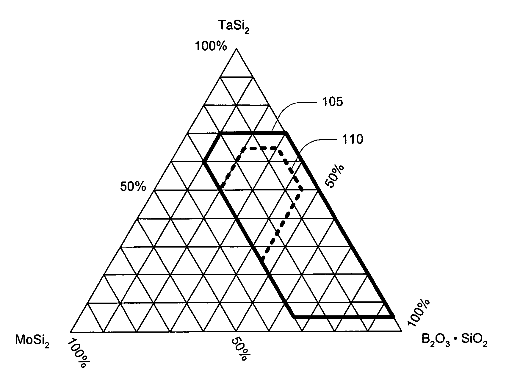
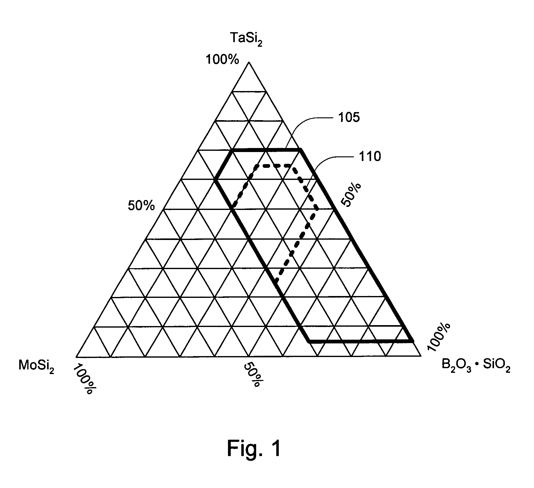
[0009]The various embodiments include high-efficiency tantalum-based ceramics. These low catalytic efficiency and high emittance ceramic materials were developed in order to increase the capability of a TUFI-like thermal protection system, with its high impact resistance, to temperatures above 3000° F. (1650° C.). These ceramics have been applied to both blunt and sharp wedge shaped configurations as well as the conventional shaped tile used on current high-speed atmospheric entry vehicles.

Problems solved by technology

This system, if breached, has resulted in the loss of the vehicle during Earth entry.
Also, these systems are heavier, orders-of-magnitude more expensive, and require much longer lead times for delivery than a system made using rigid fibrous insulation.
Other lighter weight, less expensive alternatives including coated fibrous insulation systems (such as RCG on LI-900, a low-density fibrous silica glass structure) are susceptible to excessive surface recession and / or impact damage during launch and / or landing.
The specific disadvantages of the prior art depend upon the type of leading edge chosen.
For a structural type leading edge, the major disadvantages are weight; the complexity of designing a hot structure that must perform under load and expand from room temperature to high temperature while maintaining structural integrity and while remaining attached to the vehicle; and the cost and time required to produce appropriate parts.
For an insulating leading edge the disadvantage has been the relatively limited temperature capability of materials that has made it, under most circumstances, an impracticable choice due to the unacceptable limitations it imposes on the resultant atmospheric entry vehicles.

Method used


Image

  • High efficiency tantalum-based ceramic composite structures
  • High efficiency tantalum-based ceramic composite structures
  • High efficiency tantalum-based ceramic composite structures

Examples


example 1

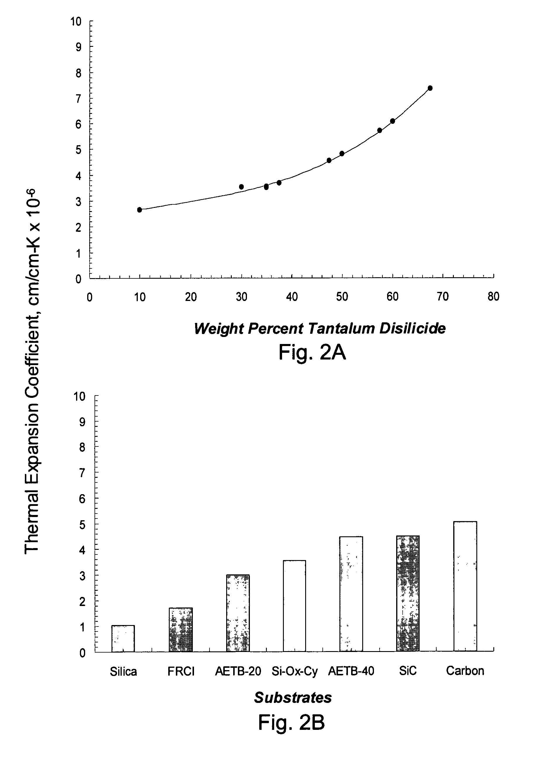
[0037]For one embodiment, a composite insulating structure substantially impervious to hot gas penetration was prepared by mixing 35% tantalum disilicide with 20% molybdenum disilicide, 2.5% silicon hexaboride and 52.5% borosilicate glass. The borosilicate glass may contain from about 1% to about 10% boron oxide, but is preferably approximately 94.25% silicon dioxide and 5.75% boron oxide. All of the components were ball milled for 65 hours in an alcohol medium at 70% solids. FIG. 6 is a graph of the approximate particle size distribution measured after one such milling. After milling, the components were diluted to 25% solids prior to spraying on a substrate, e.g., AETB-40 / 12, with a sub-layer applied. The sub-layer was composed of 55% molybdenum disilicide, 2.5% silicon hexaboride and 42.5% borosilicate glass. All of the components of the sub-layer were ball milled for 65 hours in an alcohol medium at 70% solids and diluted to 25% solids prior to application. The sub-layer compris...

example 2

[0038]For another embodiment, a composite insulating structure substantially impervious to hot gas penetration was prepared by mixing 15% molybdenum disilicide with 60% tantalum disilicide, 2.5% silicon hexaboride and 22.5% borosilicate glass. All of the components were ball milled for 65 hours in an alcohol medium at 70% solids prior to spraying on a carbon preform with a sub-layer applied. The sub-layer was composed of 20% molybdenum disilicide, 2.5% silicon hexaboride and 77.5% borosilicate glass. All of the components of the sub-layer were ball milled for 65 hours in an alcohol medium at 70% solids and diluted to 25% solids prior to application. The sub-layer comprised 40% by weight of the total surface treatment. The structure was fired at 2400° F. (1315° C.) for 10 minutes and successfully tested at above 3800° F. (2095° C.) for one minute in a high-energy arc jet flow. FIG. 7 is a photomicrograph showing the particulate nature of the insulating structure after arc jet exposur...

example 3

[0039]For yet another embodiment, a composite insulating structure substantially impervious to hot gas penetration was prepared by mixing 50% tantalum disilicide, 5% silicon hexaboride and 45% borosilicate glass. All of the components were ball milled for 65 hours in an alcohol medium at 70% solids prior to spraying on an AETB-40 / 12 substrate without a sub-layer applied. It was fired at 2225° F. (1220° C.) for 90 minutes and successfully tested at about 2900° F. (1595° C.) with observable foaming.


PUM

PropertyMeasurementUnit
temperaturesaaaaaaaaaa
depthaaaaaaaaaa
particle sizeaaaaaaaaaa

Abstract

Tantalum-based ceramics are suitable for use in thermal protection systems. These composite structures have high efficiency surfaces (low catalytic efficiency and high emittance), thereby reducing heat flux to a spacecraft during planetary re-entry. These ceramics contain tantalum disilicide, molybdenum disilicide and borosilicate glass. The components are milled, along with a processing aid, then applied to a surface of a porous substrate, such as a fibrous silica or carbon substrate. Following application, the coating is then sintered on the substrate. The composite structure is substantially impervious to hot gas penetration and capable of surviving high heat fluxes at temperatures approaching 3000° F. and above.

Description

ORIGIN OF INVENTION[0001]The invention described herein was made by employees of the United States Government and may be manufactured and used by or for the Government for governmental purposes without payment of any royalties thereon or therefore.TECHNICAL FIELD OF THE INVENTION[0002]The present invention relates generally to thermal protection systems and in particular to composite structures containing tantalum-based ceramics.BACKGROUND OF THE INVENTION[0003]Previous composite insulating structures intended for use in such applications as on orbital reentry vehicles, such as the Space Shuttle Orbiter, have consisted of a coating in combination with a low density insulation substrate. A borosilicate glass, Reaction Cured Glass (RCG), was chosen as the coating for the silica type of Reusable Surface Insulation (RSI) previously selected as the heat shield for the Orbiter, as disclosed in U.S. Pat. No. 4,093,771 issued Jun. 6, 1978 to Goldstein et al. This coating was prepared by ble...

Claims


Application Information

Patent Timeline
Patent Type & Authority Patents(United States)
IPC IPC(8): B32B7/02B32B17/06B32B27/32B32B9/00
CPCB64G1/58C04B41/009C04B41/52C04B41/89C04B35/58092C04B41/4543C04B41/5022C04B41/507C04B41/5071C04B35/10C04B35/14C04B35/18C04B35/565C04B35/52C04B38/00C04B30/02Y10T428/30C04B2111/00982C04B2235/3409C04B2235/3418C04B2235/365C04B2235/3804C04B2235/9607
Inventor STEWART, DAVID A.LEISER, DANIEL B.DIFIORE, ROBERT R.KATVALA, VICTOR W.
Owner NASA
Learn More