Multiband folded loop antenna

a multi-band, loop antenna technology, applied in the direction of loop antennas, resonant antennas, radiating elements structural forms, etc., can solve the problems of only applying technique to dual-band mobile phone antennas such as 900 and 1800 mhz, and difficulty in simultaneously covering, so as to improve the impedance matching, simplify the structure, and increase the bandwidth of the lower band

Active Publication Date: 2010-08-03
ACER INC
View PDF5 Cites 71 Cited by
  • Summary
  • Abstract
  • Description
  • Claims
  • Application Information

AI Technical Summary

Benefits of technology

[0006]Besides, another objective of the present invention is to provide a novel antenna for the mobile phone, such an antenna has the advantages of having simple structure and definite operating mechanism, easy manufacturing, and saving space in a mobile phone.
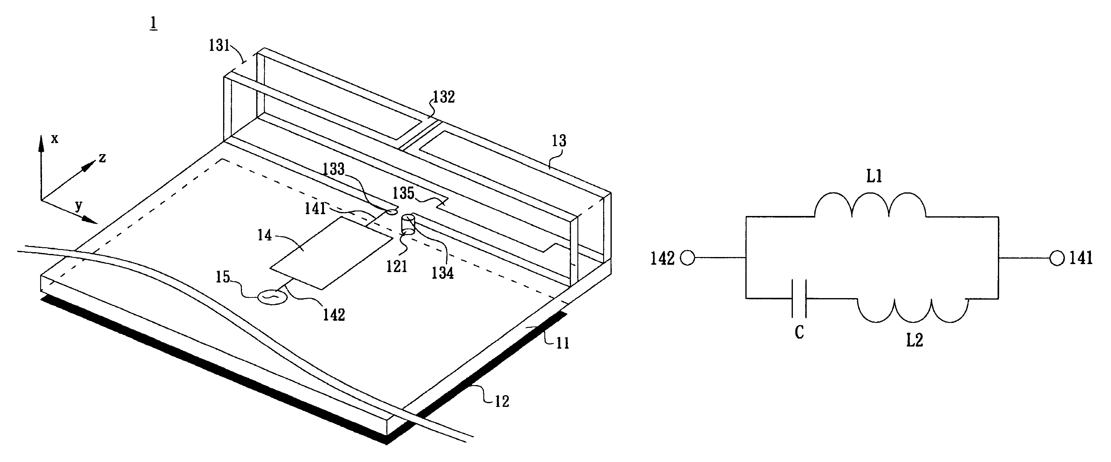
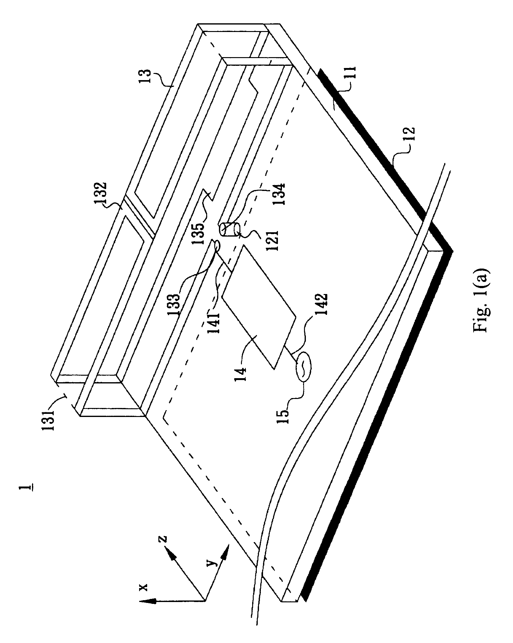
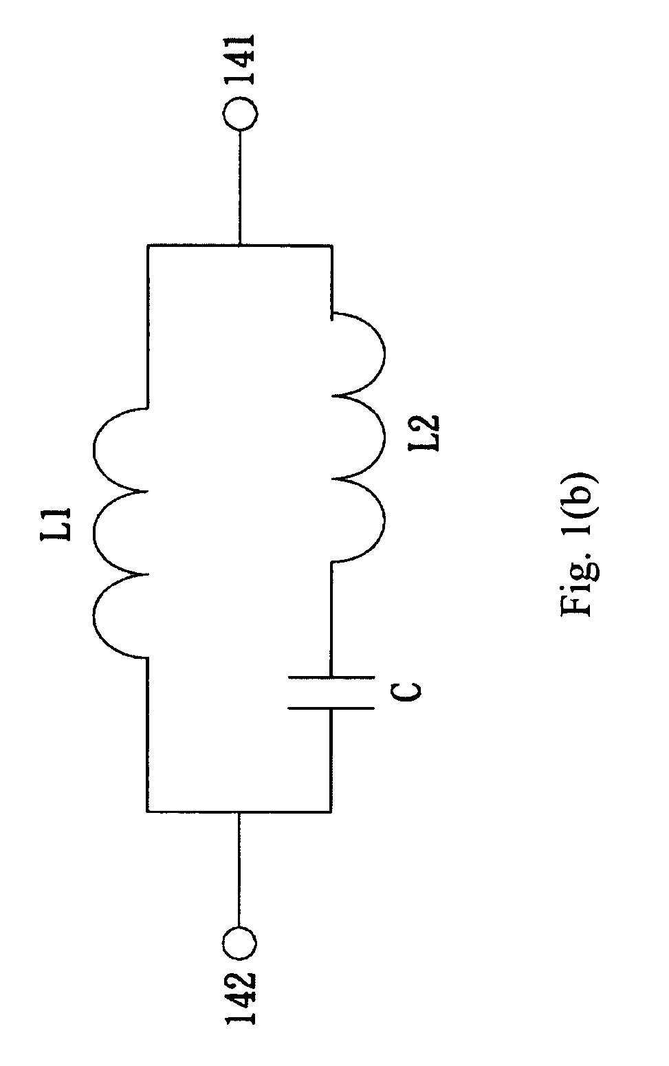
[0013]In the present invention, the 0.5-wavelength resonant mode of the loop strip is used for the lower band of the antenna, and the loop strip's higher-order resonant modes are used for the upper band of the antenna. Further, the matching circuit is used to make the antenna's first resonant mode to be dual-resonant and hence to increase the bandwidth of the lower band, and at least one tuning patch is used to improve the impedance matching over the upper band. The lower band of antenna has a bandwidth of about 200 MHz from 810 to 1010 MHz to cover GSM850 / 900 band operation (from 824 to 960 MHz). Moreover, the impedance matching of the antenna of the present invention over the lower band is always higher than 6 dB. Meanwhile, the upper band of antenna is provided with a bandwidth of about 615 MHz from 1635 to 2250 MHz to cover GSM1800 / 1900 / UMTS band operation (from 1710 to 2170 MHz), and the return loss of the antenna of the present invention over the upper band is also always higher than 6 dB to meet the application requirement. Meanwhile, the antenna of the present invention has simplified structure, definite operating mechanism, and an antenna size smaller than that of other mobile phone antennas covering the same band operation. That is, the antenna of the present invention may save the space for mounting the antenna in the mobile phone while maintains the multiband antenna characteristic. Therefore, the antenna of the present invention is greatly valuable in terms of its wide industrial applications.

Problems solved by technology

However, taking the embedded mobile phone antenna as an example, while the space inside the mobile phone allowed for the antenna is much limited than ever before, the antenna still is required to cover multiband operation in order to meet the actual demands in the wireless communication system.
However, the lower band of the loop antenna with a greatly reduced size can cover GSM850 or GSM900 operation, but has difficulty in simultaneously covering GSM850 / 900 dual-band operation.
However, U.S. Pat. No. 7,242,364 B2 only teaches the application of the above technique for the internal mobile phone antenna for single-band operation, but such a technique could not be directly applied to a dual-band (such as 900 and 1800 MHz) mobile phone antenna.
Meanwhile, such a technique is only applicable to the mobile phone antenna having a length about a quarter-wavelength of the resonant frequency of the antenna.

Method used


Image

  • Multiband folded loop antenna
  • Multiband folded loop antenna
  • Multiband folded loop antenna

Examples


second embodiment

[0025]FIG. 2 illustrates a multiband folded loop antenna 2 according to the present invention. The antenna 2 comprises a dielectric substrate 11, a ground plane 12, and a radiating portion 13. The ground plane 12 has a grounding point 121, and is located on the dielectric substrate 11. The radiating portion 13 comprises a supporter 131, a loop strip 132, and a tuning patch 135. The loop strip 132 of the radiating portion 13 has a length about a half-wavelength of the central frequency of the first resonant mode of the antenna, and has a feeding end 133 and a grounding end 134. The feeding end 133 is electrically connected to a signal source 15, and the grounding end 134 is electrically connected to the grounding point 121 of the ground plane 12. The loop strip 132 is folded into a three-dimensional structure and supported by the supporter 131. The tuning patch 135 of the radiating portion 13 is electrically connected to the loop strip 132.

[0026]Preferably, the dielectric substrate 1...

first embodiment

[0029]FIG. 4 illustrates the radiation patterns of the antenna 1 according to the present invention when providing operation covering GSM850 / 900 bands, wherein FIG. 4(a) illustrates the radiation patterns at 859 MHz and FIG. 4(b) illustrates the radiation patterns at 925 MHz. The lower band 21 of the antenna 1 covering these operating bands is the 0.5-wavelength resonant mode. As shown in FIG. 4, the radiation patterns of the 0.5-wavelength resonant mode resonating on the loop strip is similar to the radiation patterns of the conventional monopole antenna or PIFA antenna resonating at the same frequencies.

[0030]FIG. 5 illustrates the radiation patterns of the antenna 1 according to the first embodiment of the present invention when providing operation covering GSM1800 / 1900 / UMTS bands, and FIG. 5(a) illustrates the radiation patterns at 1795 MHz, FIG. 5(b) illustrates the radiation patterns at 1920 MHz, and FIG. 5(c) illustrates the radiation patterns at 2045 MHz. The upper band 22 o...


PUM


Abstract

The present invention relates to a multiband folded loop antenna comprising a dielectric substrate, a ground plane, a radiating portion and a matching circuit. The ground plane is located on the dielectric substrate and has a grounding point. The radiating portion comprises a supporter, a loop strip, and a tuning patch. The loop strip has a length about a half-wavelength of the central frequency of the antenna's first resonant mode. The loop strip has a feeding end and a grounding end, with the grounding end electrically connected to the grounding point on the ground plane. The loop strip is folded into a three-dimensional structure and is supported by the supporter. The tuning patch is electrically connected to the loop strip. The matching circuit is located on the dielectric substrate with one terminal electrically connected to the feeding end of the loop strip and another terminal to a signal source.

Description

FIELD OF THE INVENTION[0001]The present invention relates to a loop antenna, and more particularly to a multiband folded loop antenna suitable to be embedded in a mobile phone.BACKGROUND OF THE INVENTION[0002]With the fast development in wireless communication technologies, the antenna plays an increasingly important role in various kinds of wireless communication products. Particularly, due to the tendency of developing lightweight and compact wireless communication products, the antenna size, particularly the antenna height, would decide the value of wireless communication products. However, taking the embedded mobile phone antenna as an example, while the space inside the mobile phone allowed for the antenna is much limited than ever before, the antenna still is required to cover multiband operation in order to meet the actual demands in the wireless communication system. It has been found that the loop antenna is more suitable to be internal mobile phone antenna compared to the ...

Claims


Application Information

Patent Timeline
Patent Type & Authority Patents(United States)
IPC IPC(8): H01Q11/12
CPCH01Q7/00H01Q9/26
Inventor CHI, YUN-WENWONG, KIN-LU
Owner ACER INC
Why Eureka
Try Eureka