Device and process for optical distance measurement

a technology of optical distance measurement and optical device, which is applied in the direction of distance measurement, instruments, surveying and navigation, etc., can solve the problems of significant interference with the functioning difficult to use the coherent light of the laser diode, and difficult to achieve the effect of avoiding interference effects and essentially constant reflection effects

Inactive Publication Date: 2010-08-03
VOITH PATENT GMBH
View PDF18 Cites 13 Cited by
  • Summary
  • Abstract
  • Description
  • Claims
  • Application Information

AI Technical Summary

Benefits of technology

[0020]The present invention utilizes a superluminescent diode (SLD). Like laser diodes, light from an SLD is emitted from a very small area, which is advantageous for the light source of the sensor according to the invention. Moreover, the coherence length for a SLD is only a few tens of micrometers (whereas laser diodes have coherence lengths that can be several meters), so reflections that might go back to the source will not interfere with each other. While the reflections will have an influence on the SLD's output intensity, instead of large variations with variable distance to the sheet, the reflection effect is essentially constant.
[0021]The window provides a continuous smooth surface parallel and flush with the air bearing surface, and interference effects are avoided by using an SLD with a coherence length of only a few tens of micrometers.
[0038]According to a feature of the present invention, the process can further include maintaining a distance of 100-300 micrometers between the object and a surface of the window facing the object. Moreover, the distance can be maintained with an air bearing.

Problems solved by technology

However, a difficulty arises with optical devices using the coherent light from a laser diode.
Even small amount of coherent stray light reflected and / or scattered from the source can interfere with the measurement of the relatively small amount of light backscattered from the object being measured.
Also, very small amounts of light reflected back into the laser diode can cause significant interference with the functioning of the laser diode.
Of particular difficulty are reflections from optical surfaces such as windows, beam splitters and lenses because the reflected light often follows the same path as the light to be measured.
While anti-reflection coatings reduce reflected light to a fraction of a percent, with an intense source even this fraction is sufficient to cause problems.
However, reflected light traveling the same path as the light being measured is allowed through the pinhole into the detector and can interfere with the measurement.
Moreover, it is known to use an air bearing supported sensor to follow the sheet, but such sensors must be very small and light.
However, this small size results in a light source located very near the sheet, such that the resulting optical light path to be measured is very short.
If the source is a laser diode, this optical feedback is still coherent with the outgoing beam and can cause significant changes in the output amplitude.
With a fixed distance from the source to the window and a variable distance to the sheet, the two reflections from the window will interfere with the reflection from the sheet in such a way that the interference will be either destructive or constructive depending on the distance from the window to the sheet.
Thus, the intensity of the light reflected back into the light source will not be constant, making the feedback effect very serious.
The reflection from the inner side of the window will be attenuated naturally because it is relatively far from the focal area near the sheet, but the outer side of the window is very close to the sheet and the reflection from that surface will almost inevitably end up going back to the light source, particularly because the sensor has been miniaturized so that it can be supported by an air bearing.
While both of these methods reduce the feedback effect, they also reduce the available signal intensity significantly.
These methods complicate the design, and the outer side window surface, which is most likely to cause the problem, should be flat and parallel with the sheet, i.e., it will be at least nearly perpendicular to the optical axis.
Cleaning the surface would also eventually destroy the coating.

Method used


Image

  • Device and process for optical distance measurement
  • Device and process for optical distance measurement
  • Device and process for optical distance measurement

Examples


Embodiment Construction

[0060]The particulars shown herein are by way of example and for purposes of illustrative discussion of the embodiments of the present invention only and are presented in the cause of providing what is believed to be the most useful and readily understood description of the principles and conceptual aspects of the present invention. In this regard, no attempt is made to show structural details of the present invention in more detail than is necessary for the fundamental understanding of the present invention, the description taken with the drawings making apparent to those skilled in the art how the several forms of the present invention may be embodied in practice.

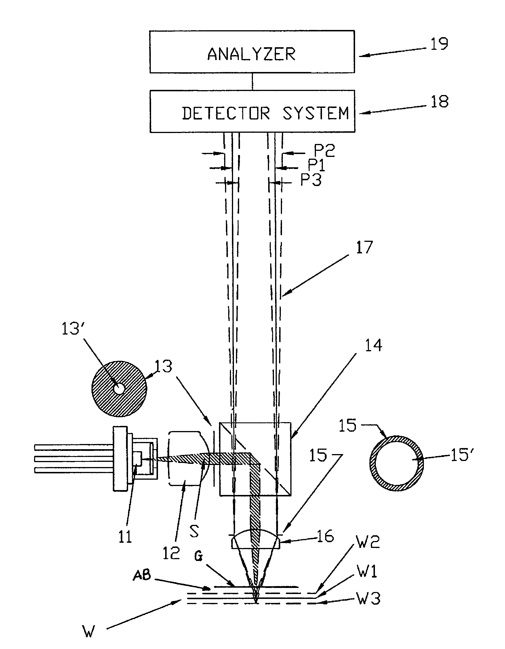
[0061]The present invention combines features of a confocal sensor supported on an air bearing with features of laser triangulation. As shown in FIG. 1, a light source 11, e.g., a low coherence light source, such as a superluminescent diode (SLD), generates a source beam S directed through a lens or lens system 12 through...


PUM


Abstract

Device and process for determining a distance to an object. The device includes a low coherence light source, at least one lens arranged to focus light from the low coherence light source onto the object and to collect light reflected and scattered from the object, and a window arranged between the lens and the object. An apertured element includes a circular aperture structured and arranged to form a circular light beam from the reflected and scattered light, and a detector system is structured and arranged to receive the circular light beam. The detector system is sensitive to light beam diameter. Further, a determining device is structured and arranged to determine a distance to the object based upon signals from the detector system.

Description

CROSS REFERENCE TO RELATED APPLICATION[0001]The instant application is a Continuation-in-Part of U.S. patent application Ser. No. 11 / 383,089 filed May 12, 2006, the disclosure of which is expressly incorporated by reference herein in its entirety.BACKGROUND OF THE INVENTION[0002]1. Field of the Invention[0003]The invention relates to an optical distance measuring device and process in a web production machine, e.g., a paper or board machine, for measuring a parameter of the web, e.g., web thickness, surface roughness, etc. More particularly, the invention relates to an air bearing supported optical distance measuring device measuring a distance to the web.[0004]2. Discussion of Background Information[0005]Known optical distance measurement in the micrometer range is generally based on either laser triangulation or confocal principle. Laser triangulation is accomplished by a device projecting a small spot of light onto a surface. A lens having an optical axis oriented at an angle to ...

Claims


Application Information

Patent Timeline
Patent Type & Authority Patents(United States)
IPC IPC(8): G01C3/08
CPCG01B11/0691G01B11/303
Inventor TYPPO, PEKKACHASE, LEE
Owner VOITH PATENT GMBH
Why Eureka
Try Eureka