Method for producing composite layers using a plasma jet source

a plasma jet and composite layer technology, applied in the field of plasma jet source production method, can solve the problems of low mechanical strength of deposited layers, high roughness, and low homogeneity of deposited layers having different functionalities

Inactive Publication Date: 2010-08-10
ROBERT BOSCH GMBH
View PDF10 Cites 54 Cited by
  • Summary
  • Abstract
  • Description
  • Claims
  • Application Information

AI Technical Summary

Benefits of technology

[0009]The method according to the present invention may provide the advantage that the gaps existing between PACVD processes and plasma spraying processes are filled and at the same time the production of innovative layer systems and materials is made possible.
[0010]For this purpose, a plasma jet source in a new process management in a fine vacuum up to an almost atmospheric pressure range renders possible a targeted, local coating process or deposition process on a substrate, the species (precursors) forming the layer are supplied to the plasma jet source or the plasma in the form of gases, fluids, or powders.

Problems solved by technology

Consequently, layers having different functionalities are deposited at relatively high deposition rates yet do not attain the homogeneity and compactness of typical PACVD layers (physically aided chemical vapor deposition) or CVD layers.
The disadvantage of this method is first the high roughness and low mechanical strength of the deposited layers, which is due to the fact that the supplied powder particles in the plasma jet are only subjected to the high plasma temperatures of partially more than 9000 K for a short time due to the high flow velocity of the jet, so that they are not completely fused but only superficially fused.
Therefore, such layers are not suitable as thin wear-protecting layers or hard material layers having a layer thickness of several micrometers.
Furthermore, the composition of such deposited layers has been largely limited to metals and metallic oxides to date.

Method used


Image

  • Method for producing composite layers using a plasma jet source
  • Method for producing composite layers using a plasma jet source
  • Method for producing composite layers using a plasma jet source

Examples


Embodiment Construction

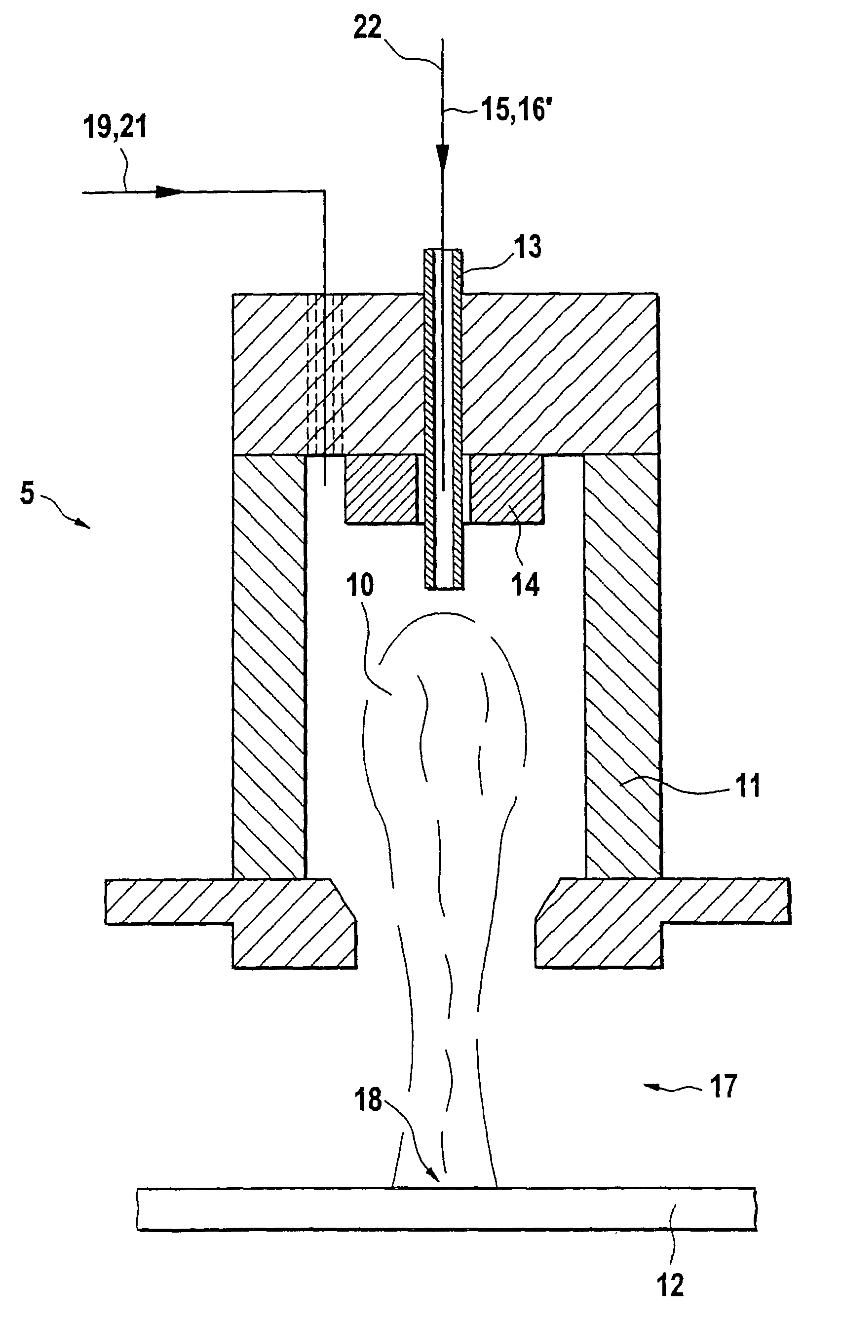
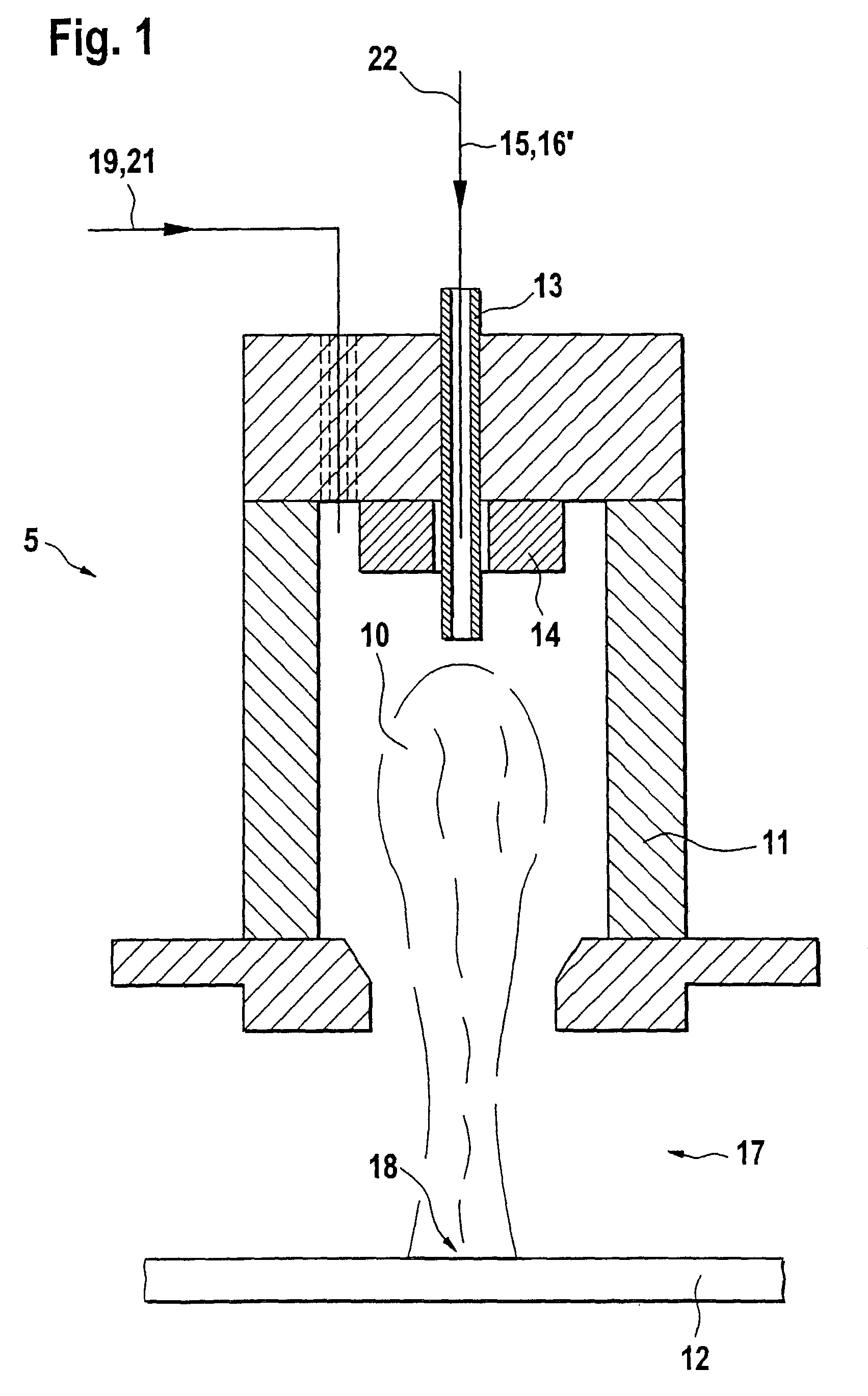
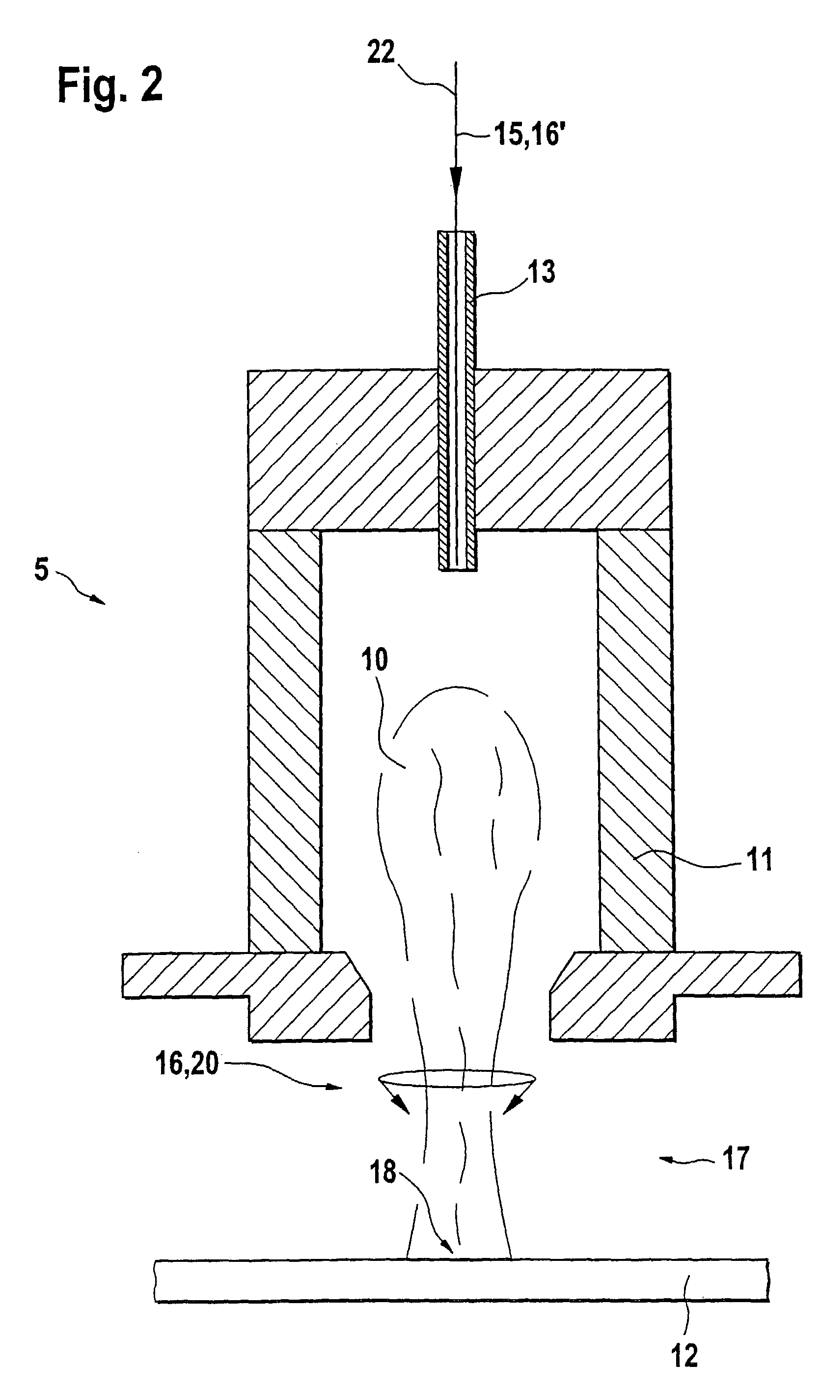
[0031]A plasma jet source 5 described in E. Pfender and C. H. Chang's “Plasma Spray Jets and Plasma-Particulate Interaction: Modelling and Experiments” symposium volume of minutes of plasma technology workshop VI, TU Illmenau, 1998, is suitable for implementing the method according to the present invention.

[0032]According to FIG. 1, an injector gas 15 is axially supplied to this plasma jet source 5 including a cylindrical torch body 11 via a feed inlet 13 and a cylindrical sleeve 14. In this context, a precursor material 16′ may also be optionally supplied with injector gas 15. In torch body 11, a plasma 10 is ignited and maintained via an electromagnetic coupling by conventional components, the plasma emerging in the form of a plasma jet 17 from torch body 11 of plasma jet source 5. Torch body 11 is a typical height of about 10 cm. Plasma jet 17 impinges at a distance of typically about 10 cm to 100 cm on a substrate 12, e.g., steel, in order to deposit a layer or a layer system th...


PUM

PropertyMeasurementUnit
temperaturesaaaaaaaaaa
pressureaaaaaaaaaa
heightaaaaaaaaaa

Abstract

A method is for producing a functional coating, e.g., composite layers or metal alloys, on a substrate using at least one plasma jet source able to be operated in a fine vacuum up to an almost atmospheric pressure range. For this purpose, the plasma jet source produces a plasma, which emerges from the plasma jet source in the form of a plasma jet and acts on a substrate. In this context, at least two precursor materials, which are modified or fused in the plasma jet and subsequently deposited on the substrate, are introduced into the plasma.

Description

FIELD OF THE INVENTION[0001]The present invention relates to a method for producing composite layers using a plasma jet source.BACKGROUND INFORMATION[0002]In many industry branches, there is a growing need for thin, hard layers having defined physical and chemical properties that are to protect components and surfaces of materials from wear or corrosion. Conventional layers are made of one or more plies having different compositions, quality characteristics, and functionalities.[0003]For this purpose, in conventional plasma spraying methods, powdery, micro-scale particles are introduced in a low vacuum up to an almost atmospheric pressure region into a plasma jet source or a plasma jet, partially fused and vaporized there, and then plated on a substrate in a targeted manner at a high speed. Consequently, layers having different functionalities are deposited at relatively high deposition rates yet do not attain the homogeneity and compactness of typical PACVD layers (physically aided...

Claims


Application Information

Patent Timeline
Patent Type & Authority Patents(United States)
IPC IPC(8): C23C16/00H05H1/24C23C14/06C23C4/123C23C4/134C23C16/30C23C16/513
CPCC23C4/121C23C4/127C23C16/513C23C4/123C23C4/134
Inventor GROSSE, STEFANVOIGT, JOHANNES
Owner ROBERT BOSCH GMBH
Why Eureka
Try Eureka