Audio-visual three-dimensional input/output

a three-dimensional input and audio-visual technology, applied in the direction of electric controllers, instruments, ignition automatic control, etc., can solve the problems of affecting the use of the keyboard, and causing the keyboard to be damaged,

Inactive Publication Date: 2010-08-10
LIN JULIUS J Y
View PDF26 Cites 134 Cited by
  • Summary
  • Abstract
  • Description
  • Claims
  • Application Information

AI Technical Summary

Benefits of technology

[0017]The present invention provides systems and methods for interaction within a virtual environment. Wherein the methods of the present invention may be utilized to virtually interact with a computer system through the use of virtual input devices, wherein the methods and systems allow a user to input data into a computing system without physical limitations.
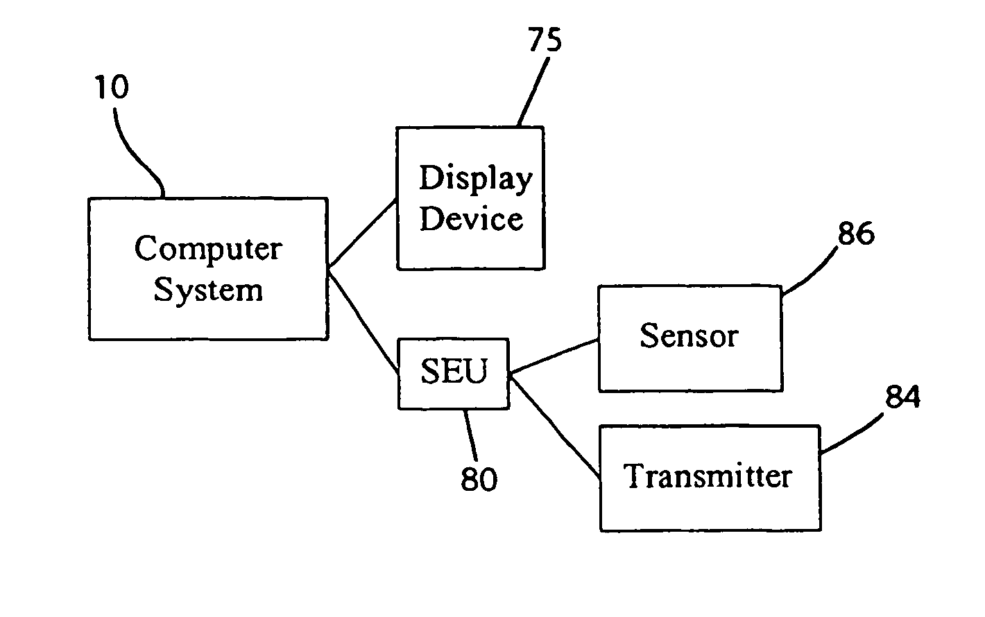
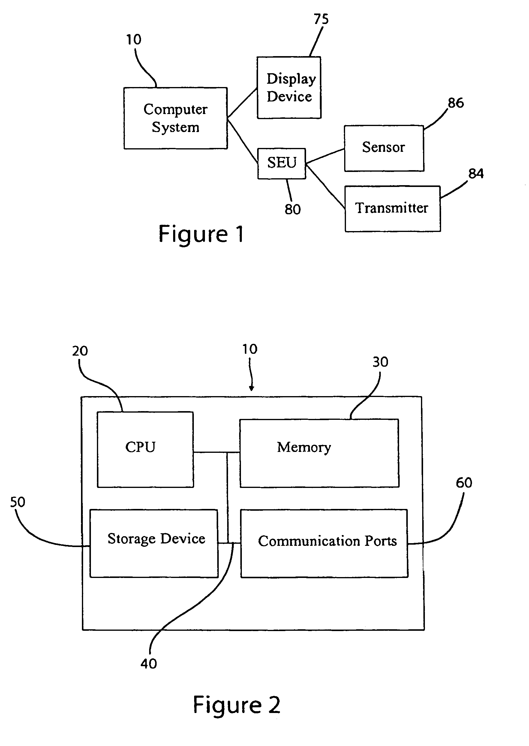
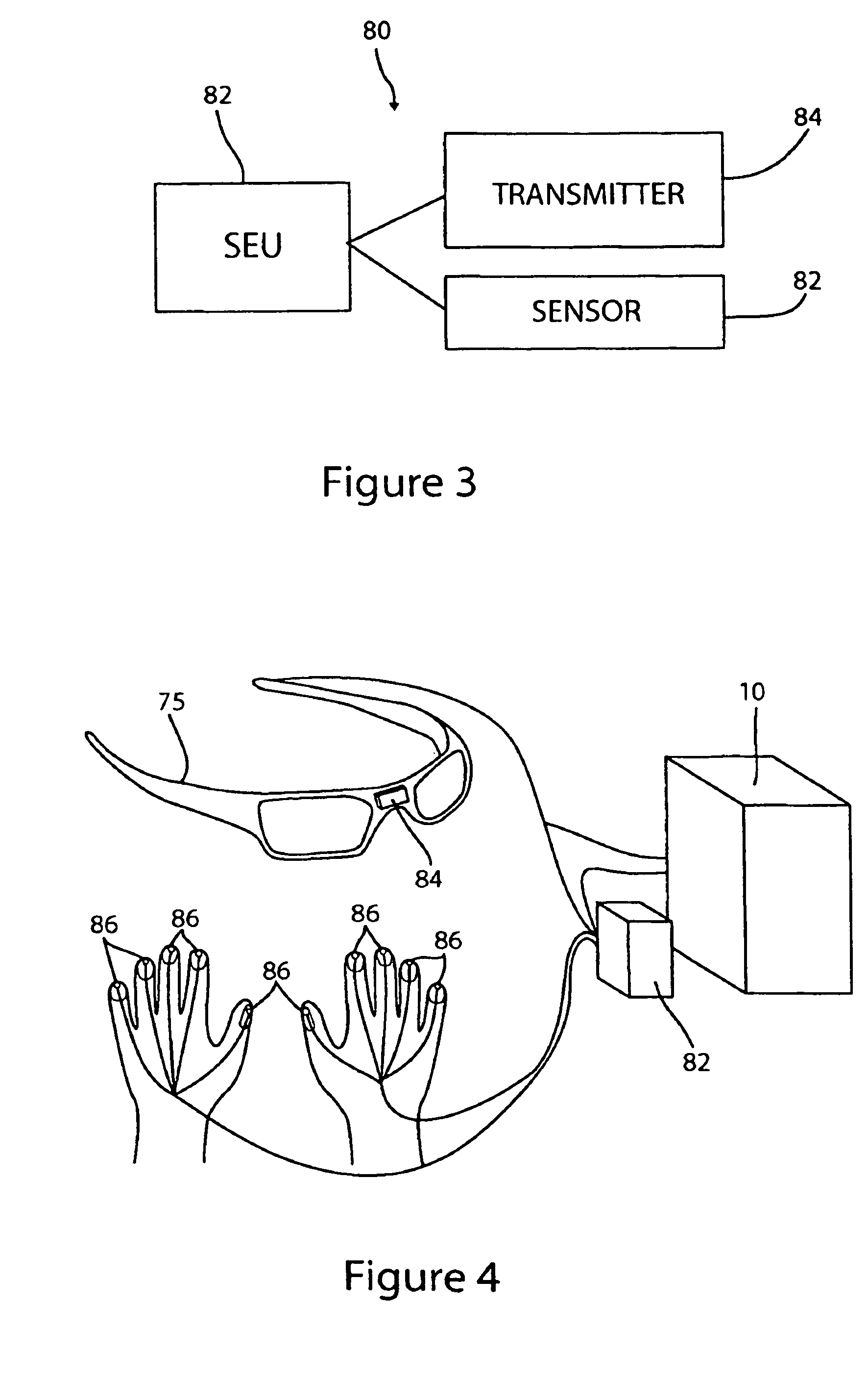
[0018]In accordance with the present invention, there is provided methods and apparatus for determining an object's three-dimensional location (i.e. real world coordinates) using audio, video and / or infrared detection techniques. According to these particular methods and apparatus, no sensors mounted on objects are required to determine location data, as may be required in other embodiments disclosed and claimed in this disclosure. Instead, a first detection device (e.g. a camera) is used to capture images of the objects, which can be used to compute location data corresponding to a first two-dimensional plane. A second detection device (e.g. microphone or infrared detector) may be used to collect additional location data in a second plane, which when combined with image data from the captured images, allows the determination of the real world coordinates (x, y, z) of the object. Objects may comprise, for example, the fingers of a user. By determining and tracking the three-dimensional coordinates of multiple objects (e.g. fingers of a user's hand) over time, real-time, real world coordinate data is generated.
[0029]There is also a need for a system that recreates a full desktop computing experience without requiring the space needed for a full desktop computer or physically limiting a user to a physical location to utilize such a system.
[0030]There is an additional need for a system that can be utilized to minimize computer related injuries such as repetitive stress injury, carpal tunnel injuries and other such injuries that are related to physical computer use.

Problems solved by technology

While computer keyboards are widely accepted and quite suitable in many situations, keyboards are not always the most efficient, convenient, or easy to use devices.
A drawback of computer keyboards is that they include up to 110 individually marked keys mounted to a base with as many switches.
All of these components must be produced and assembled, which accounts for considerable expense.
Since keyboards are mechanical, are also more prone to failure than solid-state devices, additionally, due to the likelihood of failure, broken keyboards additionally present disposal problems.
Further, the conventional keyboard cannot be quickly changed to a new keyboard layout, such as might be desired by those who have learned a keyboard layout other than the somewhat inefficient but traditional QWERTY layout.
Another drawback of computer keyboards is that they are built generally in one size for all users.
As a result, users with relatively small or large hands must adapt to a keyboard size that is not optimal for their particular hand size.
A person with smaller hands must stretch further to strike a key some distance from a home row of keys, whereas a person with larger hands will have a harder time accurately striking any desired key.
Keyboard size that is optimized for a particular use may lead to decreased hand fatigue.
Since keyboards are produced having only one size forces a user to type with his hands close together in an unnatural manner.
Additionally, as computers become more common in the workplace, a greater number of injuries have been reported due to utilizing a keyboard.
A problem with this type of system is that the user must still physically interact with a surface to generate a signal.
A problem associated with glove-based systems is that the material from which the glove has been fabricated has a fatigue life, and therefore will eventually wear out from prolonged usage.
Additionally, a user may experience discomfort from using these types of gloves in that they may perspire inside the glove.
The perspiration may further lead to degradation of the glove.
A problem with they types of keyboards is that you can only utilize the system on a smooth clean non-transparent steady surface, additionally, if you rest your hands within the projected keyboard the sensor may interpret this motion as keystrokes, thereby resulting in errors.
Further still, since the keyboard is projected onto the surface, the user may experience light interference from surrounding light sources.
Additionally, these devices do not allow a user to customize the layout of the keyboard or adapt the keyboard to a users specific style of typing.
In addition to being tethered to a computer, the use of physical input devices may cause injury to the user.
While this approach may be novel, presently voice recognition software has not advanced to the point of being reliable enough to replace a keyboard.
In addition to requiring more hardware, a microphone, the voice recognition software is always running within a computer's operating system, thus requiring additional computing power.
Also, voice recognition software must be custom tailored to each user's voice, inflections and / or accents, therefore once a system has been customized to an individual user other user's cannot readily utilize the system.
Another shortcoming of voice recognition systems is that it is difficult to use voice recognition for editing, browsing the Internet, graphic design and similar input intensive programs.
Additionally, constant talking may fatigue the user's voice, wherein the user's pitch and tone may change, thereby leading to additional input errors because the voice recognition software no longer recognizes the user's voice.
Further still, voice recognition systems cannot be utilized in cubicle type work environments or similar “open” type environment where noise interference from other voices may confuse the voice recognition software.
However, such pointing devices are remarkably ill suited for text data input.
While the input of alphabetical data is mentioned in the Quick disclosure, only numerical zones are illustrated and it remains unclear how such a device could possibly be used to enter the twenty-six additional characters of the alphabet, especially since the little finger is used solely for designating an “enter” key and is therefore not available for pointing to alphanumeric zones.
It is a slow and fatiguing process for people, even those fluent in sign language, to use such devices to enter a large amount of data into a computer, such as might be required while typing a patent disclosure, for example.
Further, while finger curvature is relatively easy to detect in a variety of sophisticated ways, such detection is only accomplished in one dimension.
This drawback is also evident in many “virtual reality” data manipulation gloves, which also include a variety of motion sensors on similar gloves.
As a result, such devices have limited use and are not well suited for prolonged data entry from a wide selection of character and command keys, such as those found on the standard computer keyboard.
As previously described, these gloves are generally fragile and are not constructed for constant everyday usage.
Additionally, the gloves are particularly sensitive to moisture such as sweat from the users hands or a wet environment, wherein moisture may cause sensor problems or lead to eventual failure of the glove.

Method used


Image

  • Audio-visual three-dimensional input/output
  • Audio-visual three-dimensional input/output
  • Audio-visual three-dimensional input/output

Examples


Embodiment Construction

[0081]Before the present invention is described in such detail, it is to be understood that this invention is not limited to particular variations set forth herein as various changes or modifications may be made to the invention described and equivalents may be substituted without departing from the true spirit and scope of the invention. In addition, many modifications may be made to adapt a particular situation, material, composition of matter, process, process act(s) or step(s) to the objective(s), spirit or scope of the present invention. All such modifications are intended to be within the scope of the claims made herein.

[0082]Methods recited herein may be carried out in any order of the recited events that are logically possible, as well as the recited order of events. Furthermore, where a range of values is provided, it is understood that every intervening value, between the upper and lower limit of that range and any other stated or intervening value in that stated range is ...


PUM


Abstract

Methods and apparatus for determining an object's three-dimensional location (i.e. real world coordinates) using the audio-video infrastructure of a 3G cellular phone or a 3C (Computer, Communications, Consumer) electronic device. A first detection device (e.g. a camera) is used to capture images of the objects. The captured image data is used to compute location data of the object in a first two-dimensional plane. A second detection device (e.g. microphone or infrared detector) may be used to collect additional location data in a second plane, which when combined with image data from the captured images allows the determination of the real world coordinates (x, y, z) of the object. The real-world coordinate data may be used in various applications. If the size of an object of interest is known or can be calculated, and the size of the projected image does not vary due to rotation of the object, a single camera (e.g. the camera in a 3G or 3C mobile device) may be used to obtain three-dimensional coordinate data for the applications.

Description

CROSS-REFERENCE TO RELATED APPLICATIONS[0001]This application is a continuation-in-part of prior U.S. application Ser. No. 10 / 703,184, filed Nov. 5, 2003 now U.S. Pat. No. 7,337,410, which claims the benefit of U.S. Provisional Patent Application No. 60 / 424,557, filed Nov. 6, 2002. This application also claims the benefit of U.S. Provisional Patent Application No. 60 / 591,611, filed on Jul. 28, 2004.FIELD OF THE INVENTION[0002]The present invention is generally related to methods and devices for producing a virtual computing environment. More specifically, the present invention is related to methods and devices that in combination mimic the functionality and behavior of a physical computer system in a virtual environment. In particular the methods and devices in accordance with the present invention includes a portable computing system wherein the system is configured to provide the user with a virtual hardware environment that may be utilized for computing, gaming or other uses.BACK...

Claims


Application Information

Patent Timeline
Patent Type & Authority Patents(United States)
IPC IPC(8): G05B11/01G06K9/20G09G5/00G09G5/08G05B15/00G06K9/00G01B11/14G01B11/30G06K9/36
CPCG06F3/011
Inventor LIN, JULIUS J. Y.
Owner LIN JULIUS J Y
Why Eureka
Try Eureka