
Catalyst structure

a technology of catalysts and catalysts, applied in the field of catalyst structures, can solve the problems of increasing radial temperature gradients, limiting commercial viability, and limited heat transfer performance of fixed-bed reactors

Inactive Publication Date: 2010-08-17
SHELL OIL CO
View PDF9 Cites 2 Cited by
  • Summary
  • Abstract
  • Description
  • Claims
  • Application Information

AI Technical Summary

Problems solved by technology

The heat transfer performance of a fixed-bed reactor is limited because of the relatively low mass velocity, small particle size and low thermal capacity of fluids.
If one attempts, however, to improve the heat transfer by increasing the gas velocity, a higher CO conversion could be obtained, but an excessive pressure drop across the reactor may develop, which limits commercial viability.
Increasing reactor capacity by increasing gas throughput and CO conversion may also result in increasing radial temperature gradients.
The desired use of high-activity catalysts in Fischer-Tropsch fixed-bed reactors makes the situation even more challenging.
The limited heat transfer performance makes local runaways (hotspots) possible, which may result in local deactivation of the catalyst.
However, the presence of temperature gradients within the reaction mixture means that some of the catalyst is operating at sub-optimal conditions.
A potential limitation of the trickle bed system (as well as any of the fixed-bed designs) is the pressure drop associated with operating at high mass velocities.
The gas-filled voidage in fixed-beds (typically less than 0.50) and size and shape of the catalyst particles does not permit high mass velocities without excessive pressure drops.
Consequently, the conversion rate per unit reactor volume is limited by heat removal and pressure drop.
However, the loss of catalyst selectivity and lower catalyst efficiency may make this unattractive.
In the case of multi-tubular reactors, the number of tubes incorporated is generally limited by mechanical parameters.
Other issues associated with the use of suspended catalyst particles are non-uniform distribution of catalyst throughout the reactor (with knock-on effects on cooling) and catalyst attrition.

Method used


Image

  • Catalyst structure

Examples


Embodiment Construction

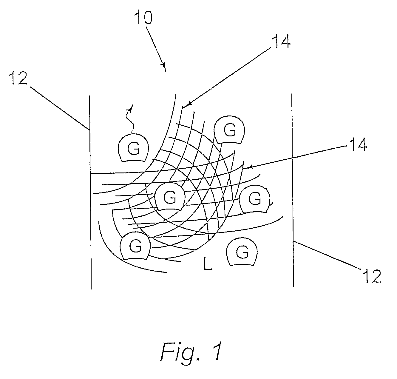
[0019]In a preferred embodiment the catalyst structure comprises one or more one porous catalyst elements fixable within the reactor, each of said porous catalyst elements being at least about 1 cm3, preferably at least about 10 cm3, in size. The maximum size of the catalyst elements may be up till several meters or even more in one or more directions. For instance woven or non-woven metal structures in the shape of large blankets may be used which suitably can be placed between several rows of cooling tubes. Such blankets may have dimensions from 2 to 10 m by 0.5 to 2 m at a thickness of 1-10 cm. The catalyst may also be in the form of rolled up blankets, e.g. cylinders of 2 to 10 m long with a diameter between 10 and 50 cm. One or more cooling tubes may be present in such a cylinder, especially at least one cooling tube in the center of the cylinder. The size usually is between 0.001 m3 and 10 mm3, suitably between 0.01 m3 and 8 m3, preferably between 0.1 and 5 m3.

[0020]It is obse...


PUM

PropertyMeasurementUnit
volumeaaaaaaaaaa
molar ratioaaaaaaaaaa
superficial gas velocityaaaaaaaaaa

Abstract

A process for the synthesis of hydrocarbons in a three phase reactor comprising the steps of: (i) introducing synthesis gas into the reactor; (ii) causing the synthesis gas to be contacted with a Fischer-Tropsch catalyst; and (iii) removing products from the reactor, wherein step (i) comprises introducing some or all of the synthesis gas into the reactor at or near the bottom of the reactor; and step (ii) comprises contacting the synthesis gas with a catalyst structure immobilised within the reactor, wherein the catalyst structure comprises one or more porous catalyst elements fixable within the reactor, each of said porous catalyst elements being at least 1 cm3, preferably at least 10 cm3, in size and wherein the open volume within each porous catalyst element is at least 60% (with reference to the volume of the porous catalyst elements) and each porous catalyst element includes a Fischer-Tropsch catalyst material.

Description

FIELD OF THE INVENTION[0001]The present application claims priority to European Patent Application 04256131.6 filed 4 Oct. 2004.[0002]The present invention relates to a catalyst structure for use in three phase bubble column reactors. In particular, the invention relates to a catalyst structure for use in Fischer-Tropsch reactions.BACKGROUND OF THE INVENTION[0003]The Fischer-Tropsch process can be used for the conversion of hydrocarbonaceous feed stocks into liquid and / or solid hydrocarbons. The feed stock (e.g. natural gas, associated gas and / or coal-bed methane, residual oil fractions, coal) is converted in a first step into a mixture of hydrogen and carbon monoxide (this mixture is often referred to as synthesis gas or syngas). The synthesis gas is then converted in a second step over a suitable catalyst at elevated temperature and pressure into paraffinic compounds ranging from methane to high molecular weight molecules comprising up to 200 carbon atoms, or, under particular cir...

Claims


Application Information

Patent Timeline
Patent Type & Authority Patents(United States)
IPC IPC(8): C07C27/00
CPCB01J19/2495B01J35/04C10G2/32C10G2/332B01J35/56
Inventor GIMPEL, FREDERIK WILLEM HENDRIKNIESEN, GERARDUS PETRUS LAMBERTUSSCHRAUWEN, FRANCISCUS JOHANNES MARIA
Owner SHELL OIL CO
Learn More