
Particle-beam exposure apparatus with overall-modulation of a patterned beam

a patterned beam and exposure apparatus technology, applied in the field of charged particle exposure apparatus, can solve the problems of difficult to achieve the timing precision of all beamlets in the range, complex internal structure, and prone to unwanted disturbing effects,

Active Publication Date: 2010-08-24
IMS NANOFABTION
View PDF12 Cites 72 Cited by
  • Summary
  • Abstract
  • Description
  • Claims
  • Application Information

AI Technical Summary

Benefits of technology

The present invention is a charged-particle exposure apparatus that includes a common deflector means and a blocking aperture means. The common deflector means adjusts the direction of incidence of the illuminating beam upon the pattern definition means, while the blocking aperture means prevents the beam from entering the substrate. The apparatus also includes a control means that generates a common blanking control signal to activate or blank out the beam. The control means can synchronize the blanking control signal with the pattern in the pattern definition means or the scanning movement of the image on the target. The invention provides improved precision in the global timing of the individual beamlets, better control over exposure dose per area, and relaxed heat load and sputter effects. It also allows for improved cooling and reduced heat load on the blocking aperture means.

Problems solved by technology

Yasuda et al., U.S. Pat. Nos. 5,430,304, 5,359,202 and 5,260,579 use a similar BAA for exposing a substrate with a pattern, but the need to fed control lines to each of the blanking apertures makes the internal structuring very complex and prone to unwanted disturbing effects such as cross-talking and transit time delays.
However, with the PLM2 layout, like with other prior art, the following main problems arise:Due to the global movement between beam and substrate, which is inherent to the PML2 or comparable prior art exposure strategy, delay times with respect to switching of beamlets automatically lead to a virtual placement error of the beamlets, independent on the position of the respective aperture on the multi-aperture plate.
In any realization of PML2 it is very difficult to achieve the required timing precision of all beam-lets in the range
Such a virtual placement error may appear in the image as an additional (non-isotropic) contribution to the blur, or as distortion of parts of the pattern imaged to the substrate.Even if the timing of the switching is arranged to be “perfect”, it will be unavoidable that the signal edges have finite slope, giving rise to, in particular, finite times of switching “on” and “off” during which the state of the electrostatic potential of the deflection electrodes (part of the pattern definition means) is not accurately defined.
In consideration of the increased power consumption of the CMOS electronics related to the switching speed (P=I2·R) and the limited thermal conductivity of the CMOS structure in the membrane-like multi-aperture plate, this requirement can be fulfilled only at low toggling rates which appear to be too small for realistic throughput rates.Due to the data reloading process connected to switching of the beamlets electromagnetic disturbances may occur which may interfere with the beam passing the pattern definition device.
The smaller the signal edge times, the higher is the disturbance due to reloading.Another problem occurring in PML2 or other prior art is that gray level dose control is achieved primarily by programming of the data stream controlling the pattern definition device.
If data preparation is done once before the exposure and no dynamic control of the total dose is possible as in prior art, such effects give rise to errors in critical dimension and placement of the (lithographic) patterns.Another critical issue is the essential synchronization between stage position (or relative position of beam with respect to substrate) and the signal timing in the pattern definition device.
A delay of one with respect to the other will have the detrimental effect that the projected image of the pattern definition device is distorted along the scanning motion and misplaced with respect to the layout design grid and previous layers (overlay error).
Particularly in the phases where the velocity of the inert stage is not perfectly settled, e.g. near the turn around events, the synchronization requirement is critical.Another problem occurring in PML2 or other prior art is that due to the unique PML2 scanning stripe exposure strategy the dose transferred to the substrate is proportional to the toggling rate.
The first would mean an unwanted dependency between data preparation and the mechanical properties of the scanner, the second would give rise to a significant throughput reduction, depending on the achievable acceleration and jerk of the mechanical scanner system.Another problem of PML2 or other prior art relates to thermal management.
In an arbitrary exposure typically 50% of the beamlets are blanked by the pattern definition device, giving rise to a persistent significant heat transfer to the surface where the blanked-out beam parts are absorbed.
Therefore, with increasing beam current the absorbing surface will tend towards surface melting as consequence of local overheating.

Method used


Image

  • Particle-beam exposure apparatus with overall-modulation of a patterned beam
  • Particle-beam exposure apparatus with overall-modulation of a patterned beam
  • Particle-beam exposure apparatus with overall-modulation of a patterned beam

Examples


Embodiment Construction

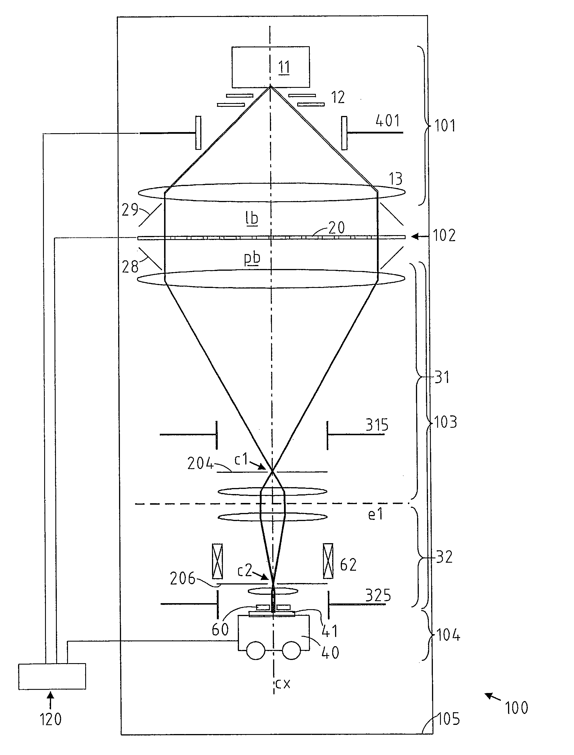
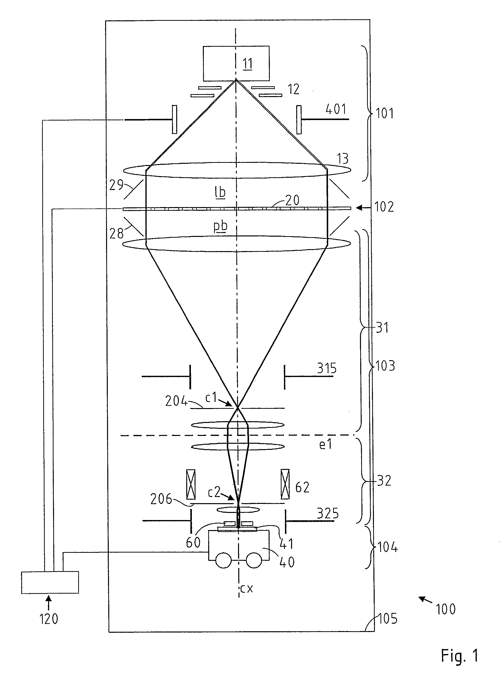
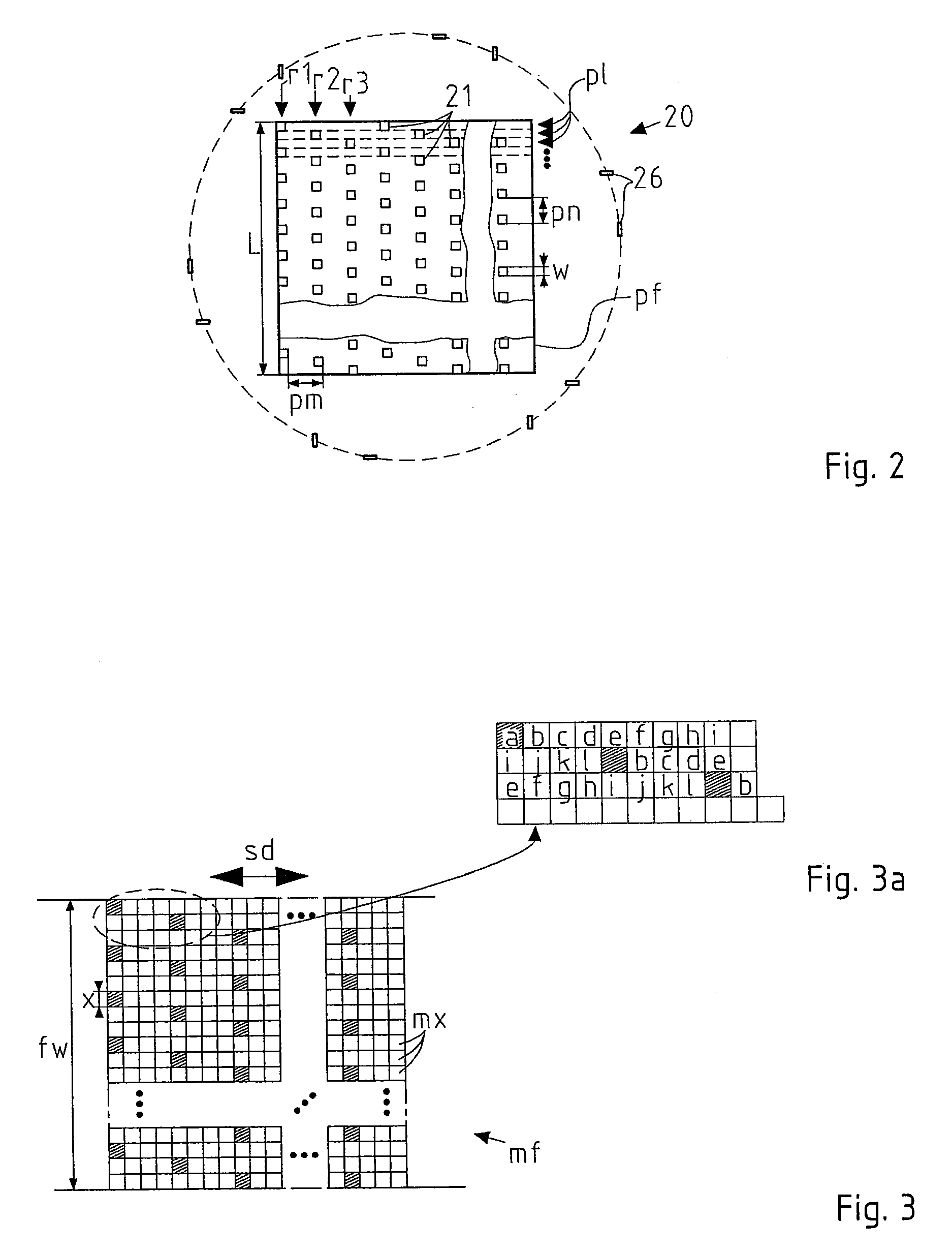
[0055]The preferred embodiment discussed in the following is based on the pattern definition (PD) system disclosed in the U.S. Pat. No. 6,768,125 and GB 2408 383 A, and the teachings of both these documents with regard to the architecture and operation of the PD device, and in particular the architecture of its blanking plate, are incorporated by reference herein. In the following, the technical background of the PD system, as far as relevant to the invention, is first discussed with reference to FIGS. 1 to 6 (which were taken, with modifications where appropriate, from the mentioned patent documents), then the preferred embodiment of the invention is illustrated in the additional Figures. It should be appreciated that the invention is not restricted to the embodiment discussed in the following, which merely represents one of the possible implementations of the invention.

[0056]FIG. 1 shows an overview of a lithographic apparatus on which the invention is based. In the following, onl...


PUM


Abstract

In a charged-particle exposure apparatus for exposure of a target with a beam of electrically charged particles, the illumination system includes a deflector device adapted to vary the direction of incidence of the illuminating beam upon the pattern definition device, the pattern definition device forms the shape of the illuminating beam into a desired pattern, and the projection optics system projects an image of the beam shape defined in the pattern definition device onto the target; the projection optics system includes a blocking aperture device having an opening and being adapted to block passage of beams traversing outside the opening, namely when the deflector device is activated to tilt the beamlet by a sufficient angle from its non-deflected path, e.g., for blanking out during the process of loading a pattern into the pattern definition device.

Description

[0001]This application is a U.S. National Phase Application of PCT International Application No. PCT / AT2007 / 000132, filed Mar. 16, 2007.BACKGROUNDField Of The Invention[0002]The invention relates to improvements of a charged-particle exposure apparatus for exposure of a target with a beam of electrically charged particles.[0003]More in detail, the invention relates to a charged-particle exposure apparatus for exposure of a target with a beam of electrically charged particles, said particle beams propagating along parallel beam paths towards the target, said apparatus comprising an illumination system, a pattern definition means and a projection optics system; the illumination system serves to produce the beam and form it into a substantially telecentric beam illuminating the pattern definition means; the pattern definition means forms the shape of the illuminating beam into a desired pattern; and the projection optics system serves to project an image of the beam shape defined in th...

Claims


Application Information

Patent Timeline
Patent Type & Authority Patents(United States)
IPC IPC(8): H01J37/147
CPCB82Y10/00B82Y40/00H01J37/045H01J37/3175H01J37/3177H01J2237/0435H01J2237/1506H01J2237/31766H01J2237/31774H01J2237/31777
Inventor PLATZGUMMER, ELMAR
Owner IMS NANOFABTION
Learn More