Taking distance images

a technology of distance images and distance measurement, applied in the field of distance images, to achieve the effects of increasing sensitivity, increasing measuring speed, and increasing rang

Active Publication Date: 2010-08-31
TRIPLE IN HLDG
View PDF12 Cites 29 Cited by
  • Summary
  • Abstract
  • Description
  • Claims
  • Application Information

AI Technical Summary

Benefits of technology

[0042]It is the object of the invention to set forth a possibility with which the said disadvantages of the prior are of current pulse TOF sensors for image talking can be overcome. The cutting of the effort in material and time for the considerable increase in sensitivity, the increase in measuring speed on taking 2D and 3D distance images, the provision of the performance capability of pulse TOF sensors in each distance picture element, the increase in the range and the avoidance of an error independent of the distance should in particular be achieved.
[0046]With a suitable time measurement circuit, a parallel processing of start pulses of a plurality of lasers and of signal and noise pulses of a plurality of receivers in a plurality of time measuring channels arranged in parallel to significantly increase the measuring rate.
[0051]Processing of a number of echo pulses during the TOF to be able to evaluate reflections both from e.g. rain, snow, fog and a contaminated termination plate and from multiple targets in each time measuring channel, that is to permit external measurements under poor weather conditions or also to detect these problems in a metrological manner.
[0056]In comparison with stereoscopic image taking with e.g. two CCD cameras in which light per picture element is converted into charge, the charges are integrated over a time period and then read out serially, that is the light used does not have to be generated beforehand and only one path (reception) has to be provided technically, the substantial challenge in the distance image taking by means of the pulse TOF method consists of the fact that here first an electromagnetic and directed beam or part beam has to be generated per distance picture element and then its TOF per picture element has to be measured, that is that two paths have to be provided from a technical aspect. The effort per picture element is therefore substantially higher. There are, however, substantial advantages of the pulse TOF method.
[0057]The TOF of the pulses is substantially shorter in comparison with the integration time with CCD cameras, which corresponds to a substantially shorter measuring time. The integration time must also be extended due to a plurality of repetition measurements with CCD distance cameras in which a strong light pulse is transmitted and the integration time of a single pulse lies in the range of the TOF. By a skilful multiple utilization of an array of distance measuring channels for the parallel taking of a plurality of distance image points, this shorter measuring time in the pulse TOF method can be used in that a distance measuring channel is not provided for each distance picture element, but that this array is used a multiple of times sequentially for a number of distance picture element groups and the distance image is assembled from the distance picture element groups. This approach is still more expensive than a CCD chip since the limited array and the means for multiple utilization still have to be made available, but the performance capability of a distance measuring channel with the pulse TOF method with its advantages is obtained at each distance measuring point. A distance measuring channel array with performance features of the pulse TOF sensors and means for multiple utilization for distance image taking is made possible by the invention, whereby new applications, which will be looked at in more detail in the following can be realized in an economical and technical aspect.
[0058]The sensitivity of a pulse TOF measuring channel can be increased significantly with the known KEM principle already mentioned above while avoiding the above-mentioned computing effort. The invention makes apparatus possible in which the measuring speed can generally be significantly increased by means of highly integrated time measurement ICs which include a time measuring channel by massive parallel processing in the presence of a number of parallel and serial signal inputs. It is set forth here how many signals have to be configured by suitable transmitter and receiver arrays and combinations thereof, how the transmitter and receiver arrays can be combined with a time measurement IC, which contains a number of time measuring channels, and with deflection units and carriers to obtain apparatus with which a taking of distance images can be done fast, precisely, with a high range, with high lateral and distance resolution and suitable for external applications.

Problems solved by technology

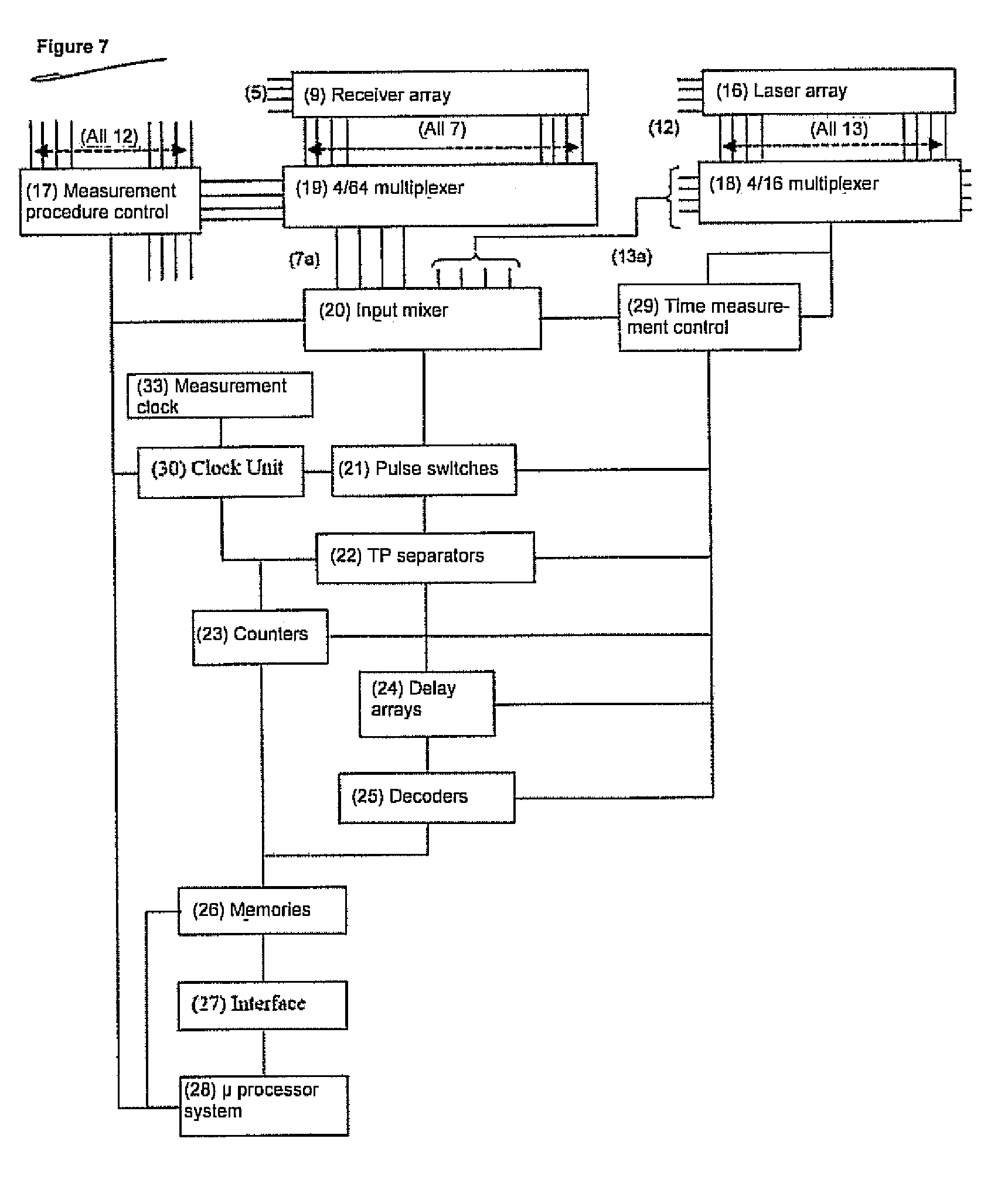
The time measurement circuits or parts thereof are configured in a number of cases as an integrated “time measurement IC” due to the required switching speeds and complexity.
Existing sensors are generally limited in their speed of taking the measured value by the maximum pulse repetition rate of the laser modules used.
This is very slow in comparison with purely imaging sensors such as CCD cameras and is not suitable for the detection of dynamic processes within the spatial angle taken.
However, the technical effort is enormous because the conversion rate has to be at some GHz and the computing effort for the averaging is necessarily proportional thereto.
For this reason, sensors of this type have not achieved any importance in the market so that the sensitivity limit of today's pulse TOF sensors is generally larger than / equal to 4.5 NEP.
It is therefore a disadvantage of the prior art thatthe sensitivity (minimal signal-to-noise ratio) is limited to larger than / equal to 4.5 NEP since no noise pulses may be detected because they would be confusable with echo pulses and would falsify the result;only one echo pulse, in rare cases two echo pulses, can be processed during the TOF and so reflections from rain, snow, fog or from the dirty termination glass of the sensor or from a plurality of impacted targets cannot be evaluated within a TOF or even make the measurement impossible, so that external applications for pulse TOF sensors can only be realized with great limitations;no parallel processing of a plurality of signal pulses or parts of a signal pulse is possible;no larger number of pulses such as noise pulses which generally occur increasedly at a low selection of the comparator threshold during the TOP can be measured with existing time measurement circuits;no 2D distance image taking (profile) is possible without a scanner with movable mirrors;a 3D distance image talking is only possible with two scanners with movable mirrors;no sufficient speed for a 2D or a 3D distance image talking can be achieved.
Only very small ranges can be achieved with these sensors with a very large power and averaging effort so that they represent a poor compromise for all demands, with the exception of the lateral resolution.
However, it takes considerably more effort to take the distance information as digital values from one or two images taken stereoscopically, and the accuracy worsens as the distance from the imaged objects increases.
With existing sensors, the measuring speed is generally limited by the maximum pulse repetition rate of the laser modules used.
Furthermore, the mechanical strain on the mirror scanners is very high because the total number of deflections per second is equal to the product of the column and line numbers and the repetition rate of the distance image.
Generally, this is well above the mean repetition rate of the transmitters used so that existing sensors are not suitable for the taking of distance images for the named reasons alone.
It is problematic with the pulse TOF sensors known today that one or more of the following disadvantages and of the disadvantages already mentioned above is present in all sensors or measuring systems in existence today, namely that:no sufficient speed for a 2D and 3D taking of distance images can be achieved, or at best only in very slow operation;the mirror scanners are exposed to a high mechanical strain;the suitability for outside applications is very limited.
These systems suffer from a high calculation effort and from an error which increases considerably with the distance so that they only appear suitable in a very restricted application area;triangulation systems in which a laser line is scanned over an object and is measured by means of a CCD camera.
These systems have a low range and a measurement error which increases with the distance;radar systems with which e.g. aircraft in space are measured for the purpose of air traffic control or tracking or ships are measured at sea for purposes of position tracking.
These systems are, however, also only limited in their application to these cases due to the low radiation frequency used, which causes a low lateral resolution, and due to the long time of flight of the signals, so that practically no further applications have resulted.

Method used


Image

  • Taking distance images
  • Taking distance images
  • Taking distance images

Examples


Embodiment Construction

[0092]FIG. 1 shows the basic structure of a receiver comprising an APD (2) with which the optical pulses (1) reflected from a target and received via a receiving lens as a converging radiation system (48) (cf. FIGS. 12a, 21-23) are converted into electrical signals, followed by a broadband amplifier (3) and a comparator (4) with the adjustable reference (5) and the digitized output signal (7).

[0093]The elements of the receiver are assembled in FIG. 2 to form a receiver module (8). The module (8) has the digitized output signal (7) and the reference (5).

[0094]In FIG. 3, the receiver modules (8) from FIG. 2 are assembled to form a receiver array (9) and deliver the input signals (7) for the time measuring channels. If only one laser beam (14) from one laser (10) is present, part rays of an optical pulse (1) reflected by the receiver array (9) are detected. If a plurality of lasers (10) transmit an array of laser beams, then part arrays of the receiver array (9) each detect the beam of...


PUM


Abstract

A system and method for the taking of a large number of distance images having distance picture elements. Electromagnetic radiation is transmitted in the form of transmission pulses at objects, and reflected echo pulses are detected. Measurements are made by determining the pulse time of flight of the distances of objects which respectively form a distance picture element and at which the transmission pulses are reflected. A time measuring device carries out a plurality of associated individual measurements for each distance image to be taken. Stored event lists of all time measuring channels are read out and evaluated in order to convert the respective time information contained in the event lists into distance values corresponding to the distance picture elements.

Description

CROSS-REFERENCE TO RELATED APPLICATIONS[0001]This application claims priority of European Patent Application No. 06 019 388.5 filed Sep. 15, 2006.FIELD OF THE INVENTION[0002]The invention relates to a method and to an apparatus for the taking of distance images comprising a large number of distance picture elements in accordance with the independent claims 1 and 34. The invention furthermore relates to an IC module having a time measuring device in accordance with claim 64 for the carrying out of the method in accordance with the invention and / or for the apparatus in accordance with the invention.BACKGROUND OF THE INVENTION[0003]“Distance images” are here not only to be understood as two-dimensional arrangements of distance picture elements, but also one-dimensional arrangements, also called profiles, i.e. distance images which each include a single row of distance picture elements disposed next to one another.[0004]It is the object in distance measurement to measure the time betwee...

Claims


Application Information

Patent Timeline
Patent Type & Authority Patents(United States)
IPC IPC(8): G01C3/06G01S17/89G01S7/4865
CPCG01S7/481G01S7/4815G01S7/4817G01S7/4865G01S7/487G01S17/89
Inventor HIPP, JOHANN
Owner TRIPLE IN HLDG
Why Eureka
Try Eureka