Radio oscillating and radar systems

a radar system and radio oscillating technology, applied in the field of radio oscillating and radar systems, can solve the problems of high cost of oscillation, and achieve the effects of low cost, efficient oscillation sideband wave, and high-performance optical amplifier

Active Publication Date: 2010-08-31
NGK INSULATORS LTD
View PDF16 Cites 3 Cited by
  • Summary
  • Abstract
  • Description
  • Claims
  • Application Information

AI Technical Summary

Benefits of technology

[0010]According to a radar system using s sub-carrier light source such as a mode locking laser system, many signals are observed at an interval according to optional longitudinal mode in the oscillation spectrum. A plurality of radio signals are inevitably generated other than the desired signal of beat frequency. The thus generated radio signals are reflected by an object. It is thus needed to provide a frequency filter on the reception side, and to demand severe specification of passing band of a filter so as to cut many unnecessary radio signals.
[0014]An object of the present invention is to alleviate the necessity of a reception filter of severe specification of pass band and an oscillating system and an amplifier of high performance and high reliability, in a radio oscillating system for a radar system, and to provide a radio oscillating system of improved practical use.
[0059]It is thus possible to change a filter to be set in the downstream of the receiver, required in Japanese Patent publication No. 2002-162465A, to a low cost filter not requiring severe band pass property. It becomes further possible to oscillate sideband wave efficiently required for the oscillation of radio signal. It is thus possible to oscillate radio signal having an output power larger than that of a sub-carrier light source, so that the necessity of a high performance optical amplifier or electric amplifier is alleviated even when the signal is divided into plural routes. As described above, the present invention is effective for the cost reduction.
[0060]Further, according to the present invention, each of the multiplied waves of two, three, four, five and six-fold was modulated with the optical modulator and the modulated light was further opto-electrically converted with an optical receiver to electrical signal. The intensity of the electrical signal was thus studied. It was finally found that the electrical signal corresponding with a target multiplied wave can be generated and the intensity of the other unnecessary waves can be minimized, by adjusting the driving voltage Vp-p applied on the optical modulator within each range described above. It is thus possible to cut the unnecessary wave easily and to generate the target multiplied wave without the need of an electrical filter of a high precision and an optical filter. The present invention is based on the discovery.

Problems solved by technology

Such oscillation required a high cost due to the above reasons.

Method used


Image

  • Radio oscillating and radar systems
  • Radio oscillating and radar systems
  • Radio oscillating and radar systems

Examples


examples

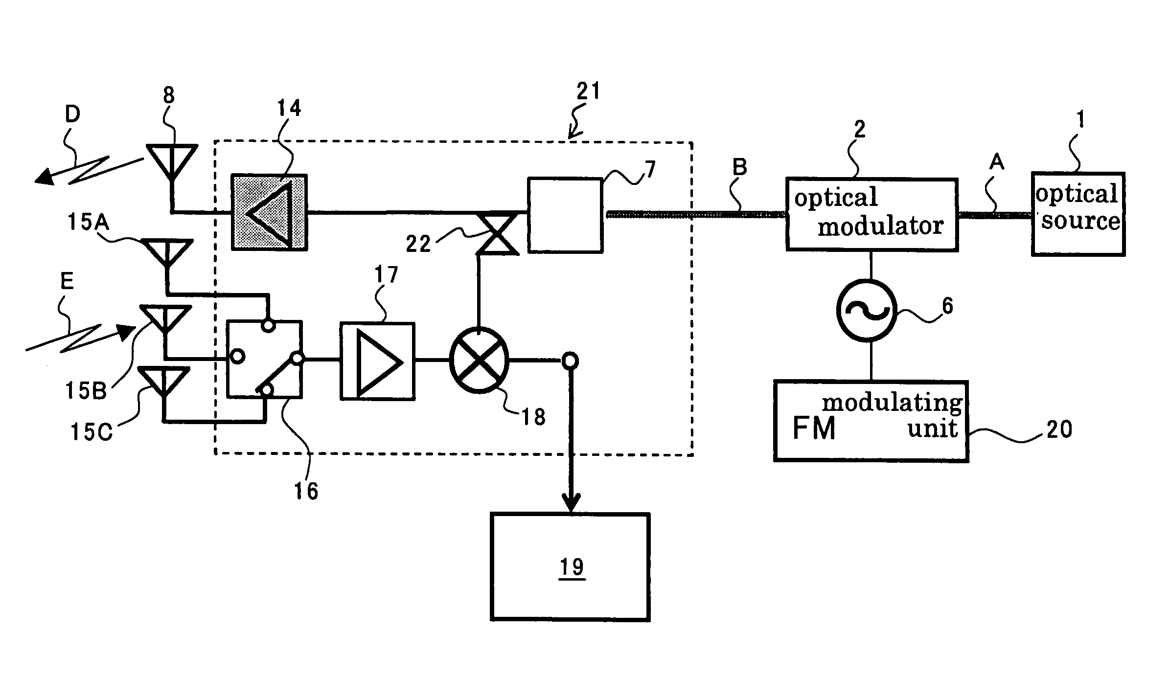
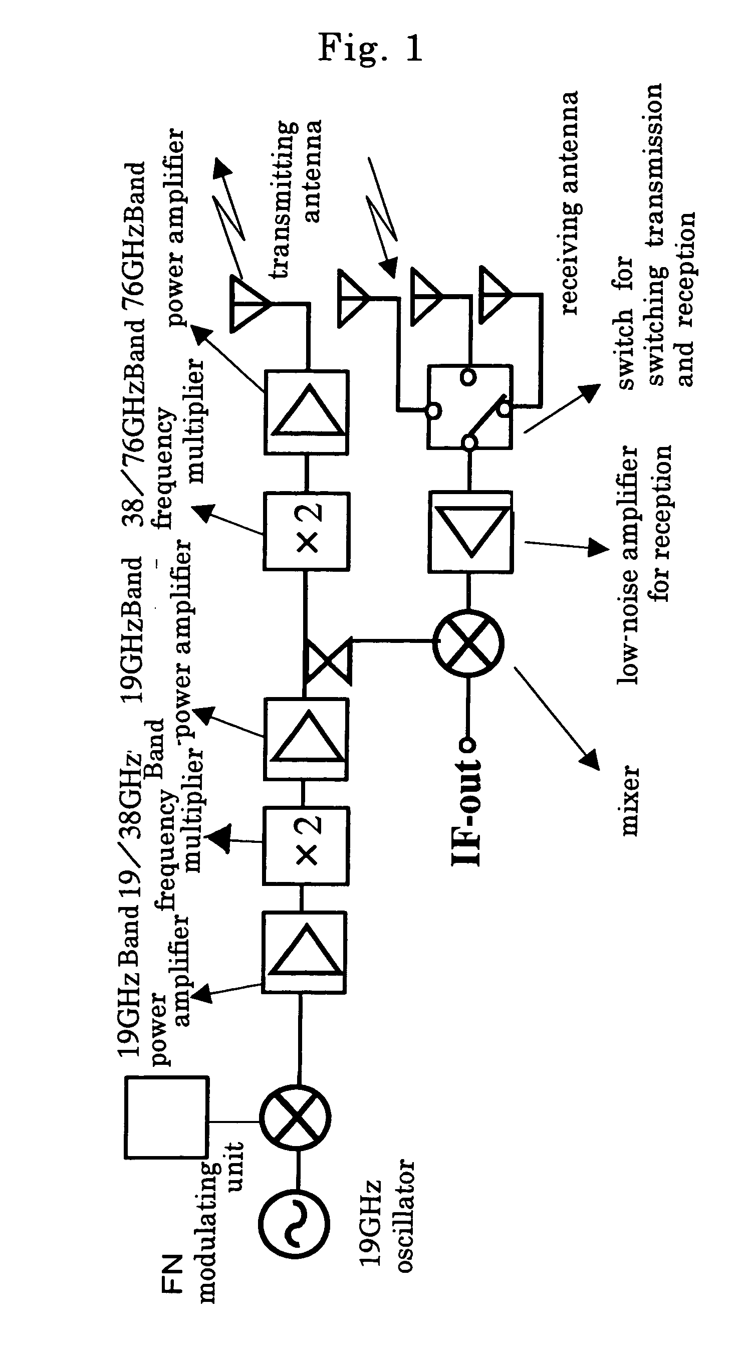
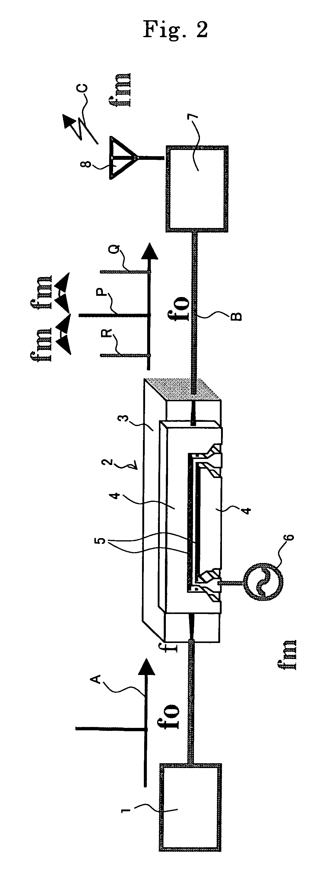
[0154]The radar system was produced using an optical modulator 2 shown in FIG. 20.

[0155]Specifically, Ti-diffusion waveguides 5A, 5B and CPW electrodes 4A, 4B and 4C were formed on a substrate of x-cut lithium niobate. As to the electrode structure, the gaps “G” between the central electrode 4B and ground electrodes 4A 4C were 20 μm, the electrode thickness was 20 μm, and the electrode length was 40 mm. The modulator substrate was adhered to a dummy plate fixed onto a surface plate with a thermoplastic resin, so that the electrode face is oriented downwardly. The substrate was then subjected to horizontal polishing and polishing to a thickness of 6 μm. A plate-shaped reinforcing body 31 of x-cut lithium niobate was adhered to the modulator substrate. The body was subjected to optical polishing at the end face of the optical waveguide and cut into chips. An adhesive having a specific dielectric constant of 4 was used as the adhesive for the fixation and the thickness of the adhesive ...


PUM

PropertyMeasurementUnit
gap widthaaaaaaaaaa
thicknessaaaaaaaaaa
thicknessaaaaaaaaaa

Abstract

It is provided a radio oscillating system for oscillating a radio signal. The system has an optical modulator for oscillation, a modulating means for inputting a modulating signal of a frequency of fm into the optical modulator to modulate a carrier wave so as to interpose sideband waves onto the carrier wave at positions shifted with respect to the frequency of the carrier wave by the frequency “fm”; and an optical receiver for oscillation for receiving beam from the optical modulator and converting the beam into an electrical signal. The system further has a radiating means for radiating radio signal of a frequency of 2fm based on the electrical signal. An input voltage Vp-p applied on the optical modulator is 1.0 times or more and 1.99 times or less of a half-wavelength voltage Vπ of the optical modulator.

Description

[0001]This application claims the benefit of Japanese Patent Application P 2005-270612 filed on Sep. 16, 2005, the entirety of which is incorporated by reference.BACKGROUND OF THE INVENTION[0002]1. Field of the Invention[0003]The present invention relates to radio oscillating and radar systems.[0004]2. Related Art Statement[0005]In Intelligent Transport Systems (ITS), it has been widely demanded a radar system utilizing radio wave such as an on-vehicle radar system. It has recently been developed, and partly commercialized, a radar system utilizing radio wave of 76 GHz band.[0006]An on-vehicle radar system is provided on the front side of a vehicle body so that it can measure the direction, distance and relative velocity of the car with respect to one running ahead of the car to function as a sensor for preventing the car accident. It will be strongly demanded an auto cruise system (ACC) controlling the speed of a vehicle and assuring the safety distance between cars. It is thus req...

Claims


Application Information

Patent Timeline
Patent Type & Authority Patents(United States)
IPC IPC(8): H04B10/00G01S7/282G01S13/931G02F1/035
CPCG01S7/352G01S13/34G01S13/87G01S13/931G01S2013/9325G02F1/0516G01S2013/9375G01S2013/9321G01S2013/93271G02F2/02
Inventor KONDO, JUNGOMITOMI, OSAMUAOKI, KENJIIWATA, YUICHIEJIRI, TETSUYA
Owner NGK INSULATORS LTD
Why Eureka
Try Eureka