Substrate holder for a vapour deposition system

a vapour deposition system and substrate technology, applied in the direction of magnets, crystal growth processes, magnetic bodies, etc., can solve the problems of non-uniform thickness of deposited films, damage to subsequent products, and relatively expensive and difficult to maintain

Active Publication Date: 2010-09-07
VIAVI SOLUTIONS INC
View PDF37 Cites 11 Cited by
  • Summary
  • Abstract
  • Description
  • Claims
  • Application Information

AI Technical Summary

Benefits of technology

[0015]wherein the cover includes an opening to expose the substrate, a lip surrounding the opening for holding an edge of the substrate against the base, and a protective region covering the end face of the base for protecting the base from stray coating material;

Problems solved by technology

The coating flux from a source in a PVD or a CVD system are relatively stable; however, they have a spatial distribution that can lead to deposited films with non-uniform thickness, if the substrates remain stationary.
To meet these demanding requirements substrate holders for high volume production are typically made of stainless, or even hardened stainless, steel, which is relatively expensive and difficult to maintain.
Unfortunately, the coating on the substrate holders builds up with each coating run and, if not removed, will flake into abrasive particles, which can cause damage to subsequent products.
Even hardened steel substrate holders wear out rapidly, resulting in that the substrate holders and the maintenance thereof are a significant cost in the coating process, and a major source of particulate generated defects.
Unfortunately, each substrate holder must be connected to a mounting flange on each spindle using mechanical fasteners, e.g. bolts, requiring manual replacement.
Not only do these mechanical systems require extra manual labor, they are more susceptible to misalignment caused by changes in temperature and pressure.
However, Shinozaki discloses a single rotating platform with a complicated levitating platform and electromagnets that totally surround the substrate holder.
Unfortunately, this approach would be impossible to implement in a planetary gear coating system, as it is very difficult to deliver power separately to individual rotating substrate holders in a planetary system, while operating in a vacuum and at elevated temperatures.

Method used


Image

  • Substrate holder for a vapour deposition system
  • Substrate holder for a vapour deposition system
  • Substrate holder for a vapour deposition system

Examples


Embodiment Construction

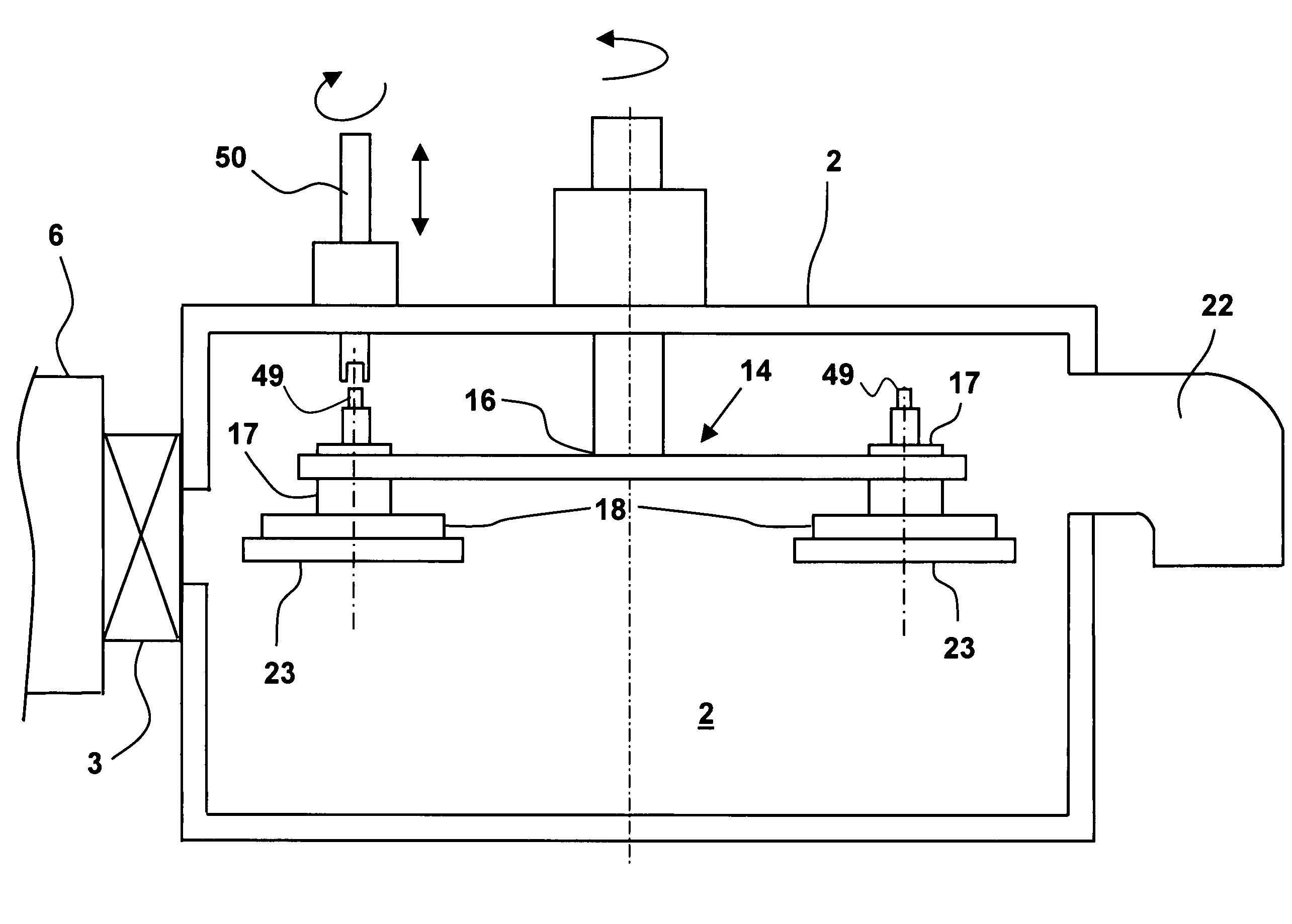
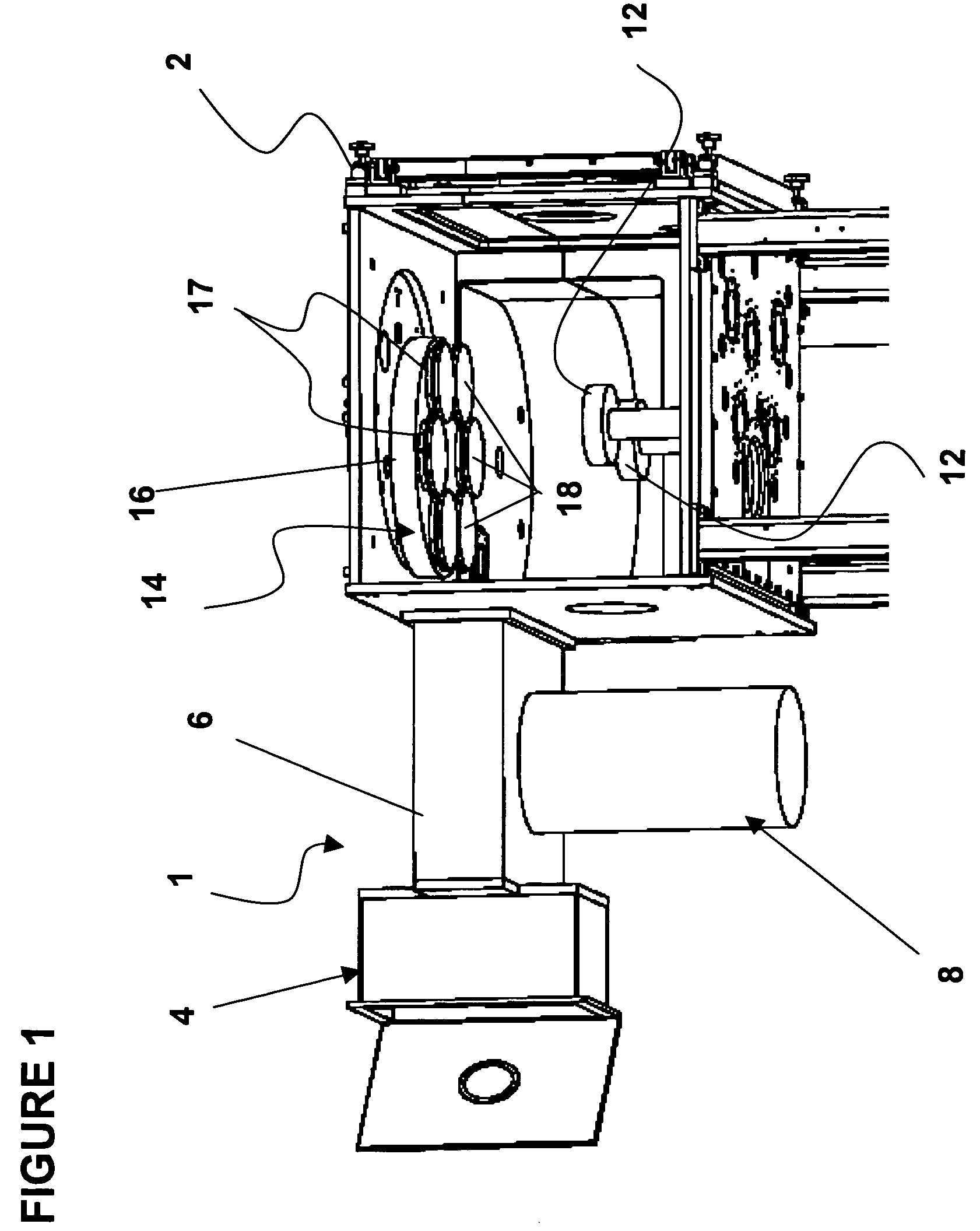
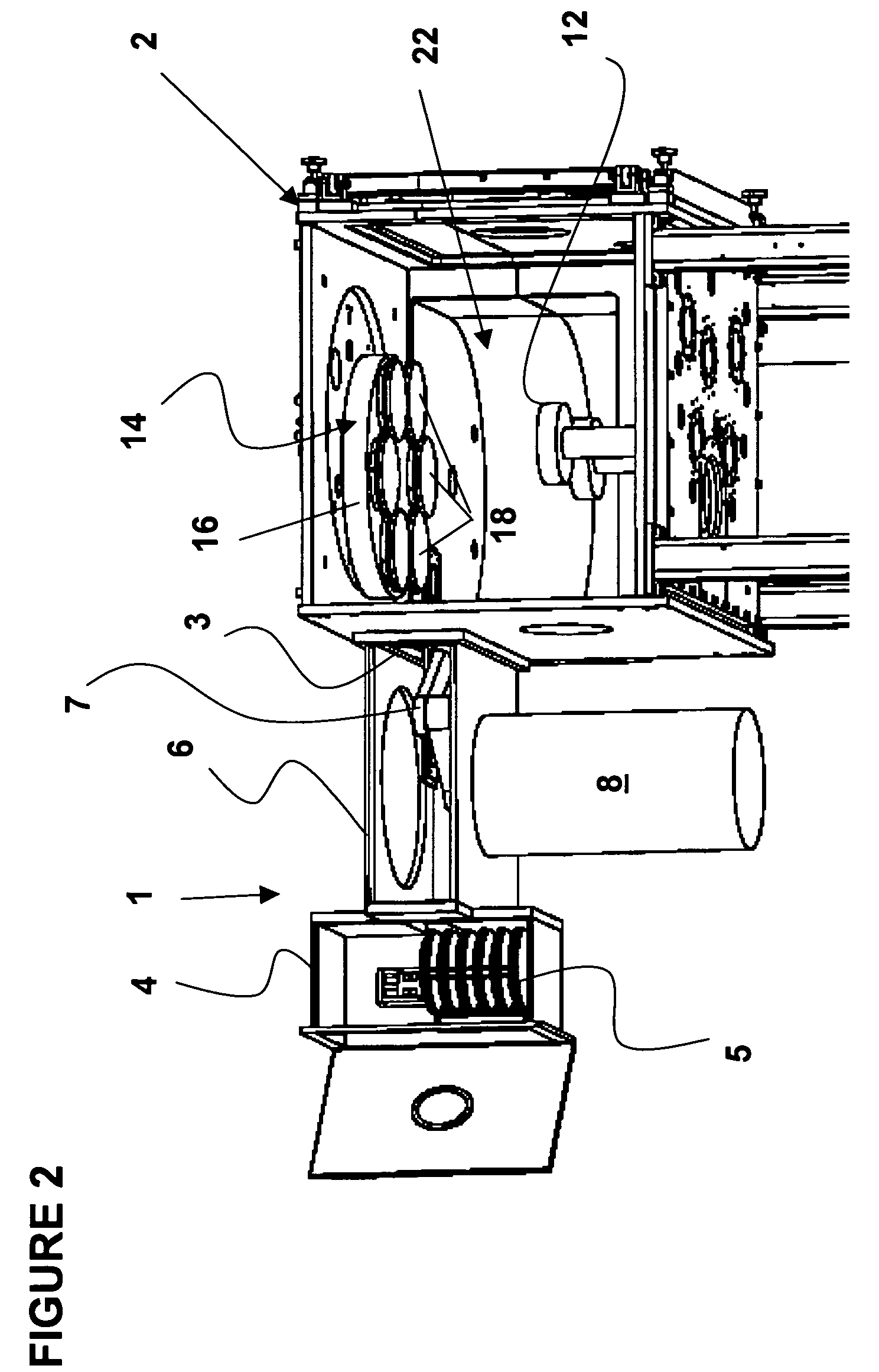
[0031]With reference to FIGS. 1 to 3, the vapor deposition vacuum system, e.g. Physical Vapor Deposition (PVD) or Chemical Vapor Deposition (CVD), according to the present invention includes a load lock chamber, generally indicated at 1, and a process chamber 2 with a gate valve 3 therebetween. The gate valve 3 enables the pressure in the load lock chamber 1 to be brought to atmospheric pressure for loading and unloading of substrates or to be re-established to the pressure of the process chamber 2 for substrate transfer, independently of the pressure in the process chamber 2. The load lock chamber 1 includes a loading container 4 with a cassette elevator 5 therein, and a transfer channel 6 with a robotic arm 7 therein. The control mechanism for the robotic arm 7 is mounted in the cylindrical canister 8 extending from the transfer channel 6.

[0032]A cathode 12, and a planetary substrate support 14 are mounted within the process chamber 2. The planetary substrate support 14 comprises ...


PUM

PropertyMeasurementUnit
thickaaaaaaaaaa
vapor pressureaaaaaaaaaa
melting pointaaaaaaaaaa

Abstract

The invention relates to a partially disposable substrate holder used in magnetic latches for securing substrates on a planetary rotating platform suspended above a coating source in a vacuum chamber of a vapor deposition system, e.g. a chemical vapor deposition (CVD) system or a physical vapor deposition (PVD) system. The substrate holder includes a reusable base formed, at least partially, from a ferro-magnetic material, which is attracted to the magnetic latch, and a disposable cover formed from a relatively inexpensive, ferromagnetic, easily formable material, which encourages adherence of coating material and has a low vapor pressure at coating temperatures.

Description

CROSS-REFERENCE TO RELATED APPLICATIONS[0001]The present invention claims priority from U.S. Patent Application No. 60 / 603,211 filed Aug. 20, 2004, and is a continuation in part of U.S. patent application Ser. No. 10 / 968,642 filed Oct. 19, 2004, which are incorporated herein by reference for all purposes.TECHNICAL FIELD[0002]The present invention relates to a substrate holder for use in a vapor deposition system, and in particular to a partially disposable substrate holder for use with a magnetic latch, which suspends the substrate holder in a vacuum chamber of a physical vapor deposition (PVD) system or a chemical vapor deposition (CVD) system.BACKGROUND OF THE INVENTION[0003]Multi-layer precision coatings, such as those used small optical systems, are commonly produced in PVD or CVD systems. Many of these coatings are applied to substrates formed of thin flat disks, which are subsequently cut to size.[0004]The coating flux from a source in a PVD or a CVD system are relatively stab...

Claims


Application Information

Patent Timeline
Patent Type & Authority Patents(United States)
IPC IPC(8): C25B9/00C25B13/00C25B11/00C23C14/00C23C16/00
CPCC23C14/505C23C16/4584C30B25/12C30B31/14H01F7/0252H01F7/04H01L21/68764H01L21/68771H01L21/68785H01J37/34H01J37/3417H01J37/32715
Inventor SEDDON, RICHARD I.
Owner VIAVI SOLUTIONS INC
Why Eureka
Try Eureka