Method of inducing refractive index structures in a micro-structured fiber, a micro-structured fiber and an article

a micro-structured fiber and refractive index technology, applied in the field of inducing refractive index structures in micro-structured fibers, micro-structured fibers and articles, can solve the problems of difficult uv-imprinting, fbg's in micro-structured fibers, and doping by itself does not provide sufficient photo-sensitivity

Inactive Publication Date: 2010-09-07
NKT PHOTONICS
View PDF15 Cites 30 Cited by
  • Summary
  • Abstract
  • Description
  • Claims
  • Application Information

AI Technical Summary

Benefits of technology

[0010]If oxygen is present in the micro-structured fiber and subjected to loading it has thus been found that under the influence of actinic radiation the oxygen and molecular hydrogen or deuterium may react to form water, H2O or D2O. The method of the invention thus prevents the formation of water during grating writing or it prevents in-diffusion of water e.g. due to condensation.
[0049]Alternatively, UV-written structures in micro-structured fiber according to an embodiment of an aspect of the invention are fabricated by sealing the ends of the micro-structured fiber by application of a fusion arc, by other form of heating and melting, by mechanical sealing or by other similar means of closing the ends prior to loading with molecular hydrogen or deuterium. This has the advantage of limiting out-diffusion of molecular hydrogen or deuterium after loading, e.g. during the UV-writing process. Furthermore, during and after cold storage of the loaded fiber, sealing of the ends prevents condensation in the vicinity of the ends of moisture that could otherwise have diffused into un-sealed holes in the micro-structured fiber.

Problems solved by technology

However, often doping by itself does not provide sufficient photo-sensitivity.
The process of imprinting FBG's in micro-structured fiber has however shown to pose a special problem, namely that it has been difficult to perform the UV-imprinting.
Water formed this way would otherwise seriously impair the grating formation process.
Water in the holes adversely affects the process of grating formation.

Method used


Image

  • Method of inducing refractive index structures in a micro-structured fiber, a micro-structured fiber and an article
  • Method of inducing refractive index structures in a micro-structured fiber, a micro-structured fiber and an article

Examples


example 1

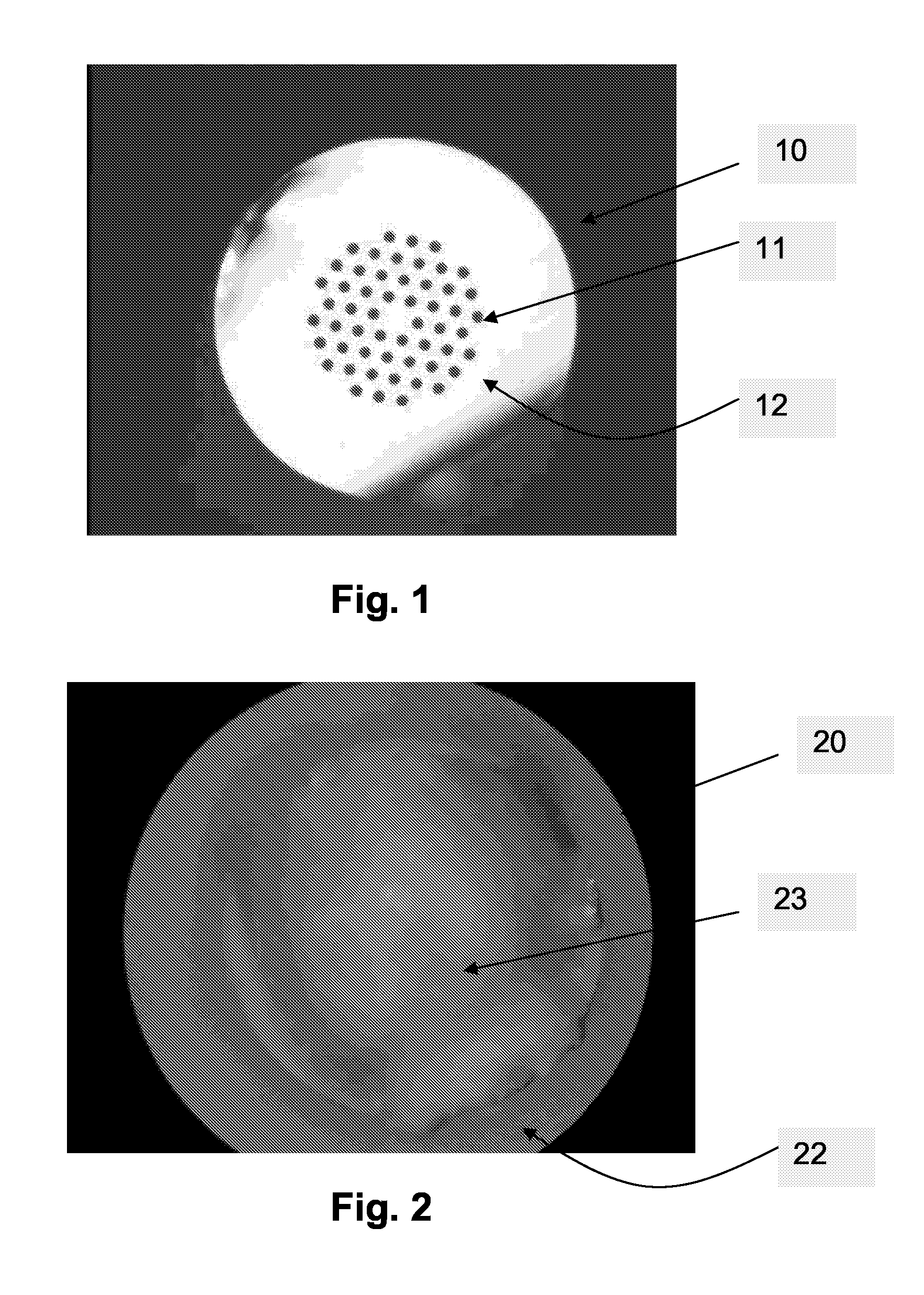
[0067]A fiber Bragg grating was made by first He-flushing a micro-structured fiber: a He-pressure bottle was connected to the holes of the micro-structured fiber via a plastic tube with low inner diameter to fit closely over the fiber. The opening between tube and fiber outer diameter was sealed using acrylate glue. The other end of the approximately 3 meter long fiber was left open. He at a pressure of 5 bar was applied for approximately 24 hours. This rather long time span was required due to the high flow resistance presented by the small size holes of the micro-structured fiber. At the end of the flushing process the open end of the fiber was sealed using acrylate glue. Subsequently the other end was sealed in the same manner, and the fiber was placed in a deuterium loading chamber at a D2 pressure of approximately 150 bar and a temperature of approximately 80° C. for approximately 24 hours. After deuterium loading a fiber Bragg grating was UV-written in the fiber using a unifor...

example 2

[0068]A fiber Bragg grating was made as described in EXAMPLE 1, only without performing the step of flushing the holes of the micro-structured fiber with a protective gas prior to the sealing of the ends of the fiber.

example 3

[0069]A fiber Bragg grating was made as described in EXAMPLE 1, only substituting the step of flushing the holes of the micro-structured fiber with a protective gas with the step of evacuating of the holes to a pressure of 0.001 atm.


PUM


Abstract

Refractive index modifications such as e.g. Fiber Bragg gratings in micro-structured Fiber are according to an aspect of the invention fabricated by first filling and / or purging the holes of the micro-structured fiber with inert gas or by evacuation and, optionally subsequently scaling the ends. Alternatively, the ends of the micro-structured fiber may be sealed without a preceding purging or evacuation of the holes. In this way hydrogen or deuterium present in the holes after photosensitizing loading will not react with atmospheric oxygen to form water. Water formed this way would otherwise seriously impair the grating formation process. Bragg gratings and other refractive index structures can thus be fabricated with high quality and predictable specifications in micro-structured fiber. Sealing the fiber ends also prevents in-diffusion of moisture. The invention may e.g. find application in connection with fiber optical sensors, high-power fiber lasers, etc.

Description

FIELD OF THE INVENTION[0001]This invention relates to the introduction of refractive index modifications (e.g. the fabrication of fiber Bragg gratings) in micro-structured fibers also known as (photonic) crystal fibers or holey fibers.BACKGROUND ART[0002]Fiber Bragg gratings (FBG) and other refractive index structures in optical fiber have found widespread applications in such technology areas as optical telecommunications, optical fiber sensors, and optical fiber lasers (cf. e.g. Raman Kashyap, “Fiber Bragg gratings”, Academic Press, 1999 (ISBN: 0-12-400560-8), referred to as [Kashyap] in the following and Andreas Othonos, Kyriacos Kalli, “Fiber Bragg gratings”, Artech House, 1999 (ISBN: 0-89006-344-3), referred to as [Othonos, Kalli] in the following). The fabrication of FBG's involves illuminating the fiber with a spatially modulated pattern of actinic radiation (typically UV-laser light). This is typically established by interference between laser beams, e.g. by transmitting the...

Claims


Application Information

Patent Timeline
Patent Type & Authority Patents(United States)
IPC IPC(8): G02B6/00
CPCG02B6/02114G02B6/02347G02B6/02361G02B6/028G02B6/032
Inventor VARMING, POUL
Owner NKT PHOTONICS
Why Eureka
Try Eureka