pH-change sensor and method

a sensor and ph technology, applied in the field of ph-change sensor and method, can solve the problems of limiting the commercialization of technology, limiting the diversification of sensors based on the same sensor platform, and requiring relatively less power to opera

Active Publication Date: 2010-09-14
THE RES FOUND OF STATE UNIV OF NEW YORK
View PDF5 Cites 57 Cited by
  • Summary
  • Abstract
  • Description
  • Claims
  • Application Information

AI Technical Summary

Problems solved by technology

CMOS fabricating techniques also offer the potential for devices that require relatively less power to operate, are small, light weight, and fast.
Most prior implementations of ISFETs with integrated recognition elements are discrete devices with specialized processing requirements that limit commercialization of the technology.
In addition, the recognition materials or elements used in such devices may be suitable only for a particular analyte, thereby limiting the diversification of the sensors based on the same sensor platform.
In most of the previous implementations, the reference electrode was an Ag / AgCl electrode, and due to its size and complexity this electrode severely limited the applicability and the advantages of developing ISFETs in a CMOS process.
However, both of these methods need post-processing of the commercially fabricated CMOS integrated circuit because a special pH insensitive layer must be deposited over the ISFET, or a different pH sensitive layer must be deposited on one of the ISFETs.
This additional processing is specialized, and therefore negatively impacts the low cost and mass-producing capabilities of using a commercial CMOS process.

Method used


Image

  • pH-change sensor and method
  • pH-change sensor and method
  • pH-change sensor and method

Examples


Embodiment Construction

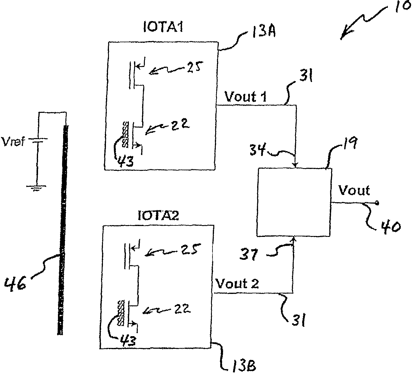
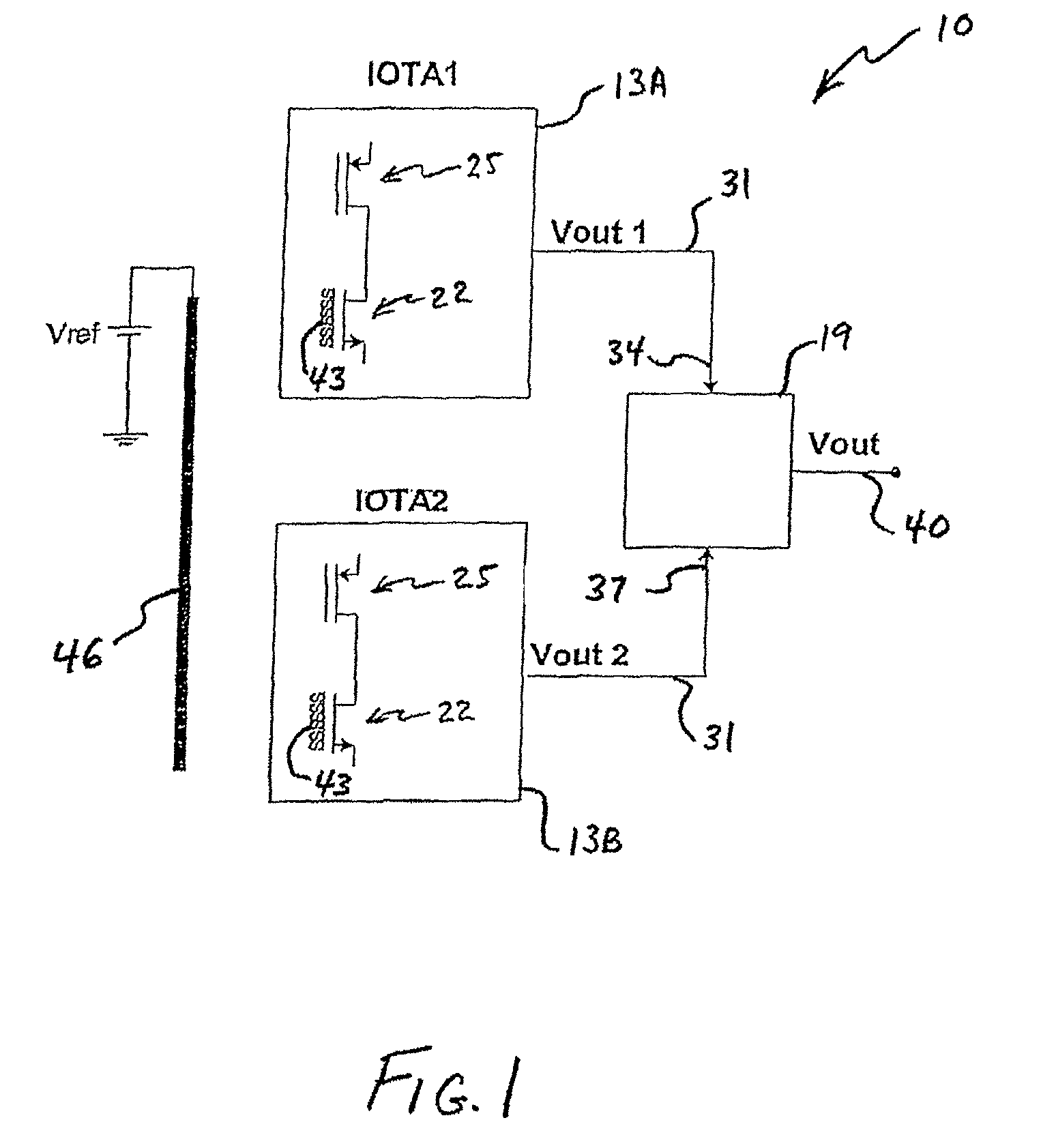
[0024]The invention may be embodied as a sensor 10 which can detect a change in pH. Such a pH-change sensor 10 may have a first ion-sensitive-transistor-operational-transconductance-amplifier (the “first IOTA”) 13A, a second ion-sensitive-transistor-operational-transconductance-amplifier (the “second IOTA”) 13B and a differential sensor 19. FIG. 1 depicts such a pH-change sensor 10.

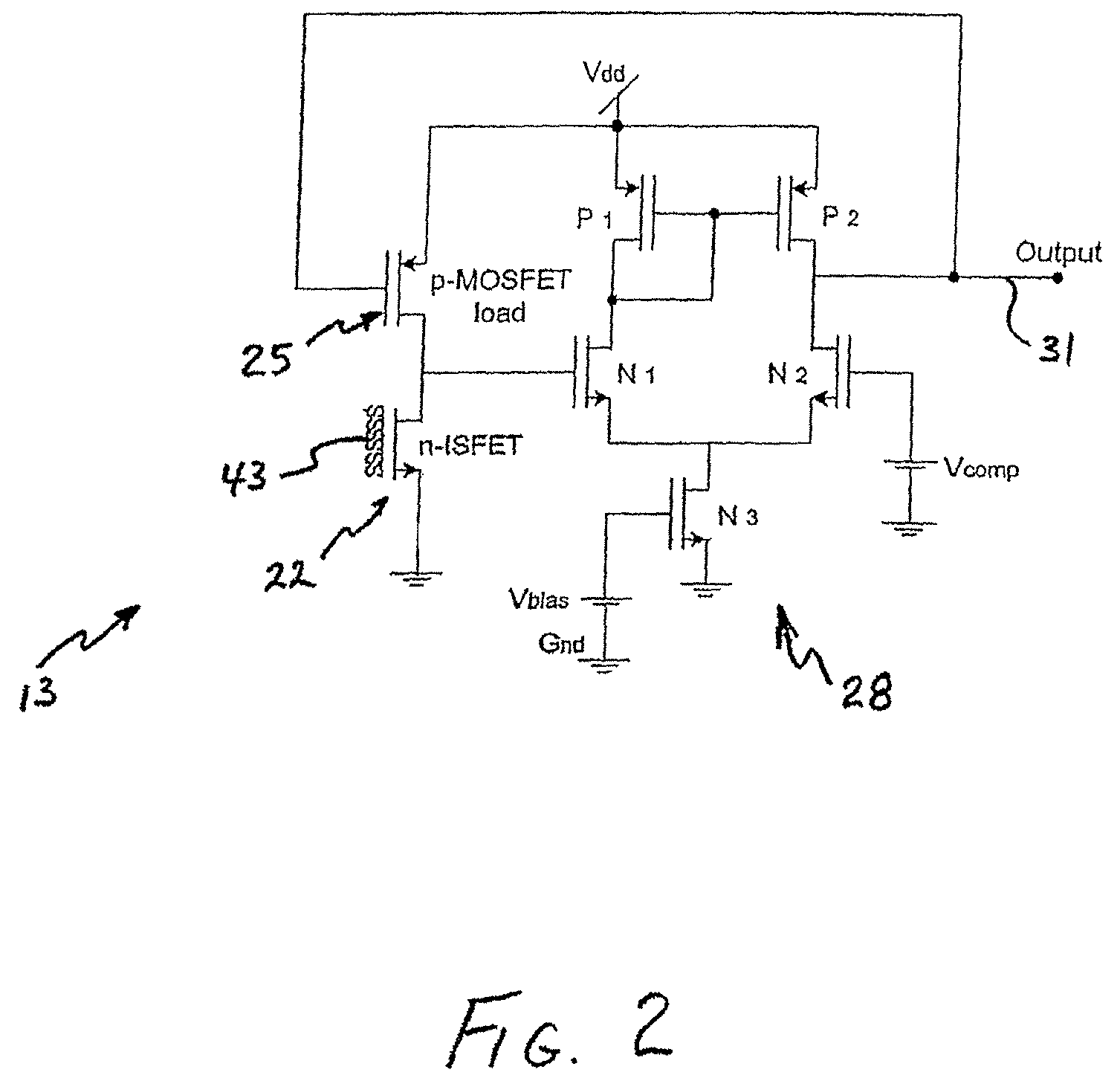
[0025]FIG. 2 depicts an IOTA 13 according to the invention. In FIG. 2 there is shown an IOTA 13, which may have an ion-sensitive transistor (an “IST”) 22, which is electrically connected to a load transistor (the “load transistor”) 25. The IST 22 in FIG. 2 is an n-channel ion-sensitive field-effect transistor (“n-ISFET”). The IST 22 and the load transistor 25 may each be a field-effect transistor. The load transistor 25 may be a metal-oxide semiconductor field-effect transistor. The IST 22 may have a drain region, a source region and a channel region that electrically connects the drain and source regions...


PUM

PropertyMeasurementUnit
poweraaaaaaaaaa
thicknessaaaaaaaaaa
thicknessaaaaaaaaaa

Abstract

pH-change sensors and related methods are disclosed. One such sensor may have a first ion-sensitive transistor-operational-transconductance-amplifier (the “first IOTA”) and a second ion-sensitive transistor-operational-transconductance-amplifier (the “second IOTA”). Each IOTA may have an ion-sensitive transistor, a load transistor, and an output. In each IOTA, the drain region of the ion-sensitive transistor may be connected to the drain region of the load transistor. A differential sensor may be connected to the IOTAs, and an output from the differential sensor may indicate a voltage difference between the IOTA outputs. The output from the differential sensor may be used to provide an indication of a change in pH.

Description

CROSS-REFERENCE TO RELATED APPLICATION[0001]This application claims the benefit of priority to U.S. provisional patent application Ser. No. 60 / 725,777, filed on Oct. 12, 2005.GOVERNMENT FUNDING[0002]This work was supported by funding from the National Science Foundation, Grant no. BES-0330240. The Government has certain rights in the invention.FIELD OF THE INVENTION[0003]The present invention relates to sensors and methods which detect changes in pH.BACKGROUND OF THE INVENTION[0004]There is a need for solid state sensors for use in many applications, including medicine, biotechnology, biomedical diagnosis, medical therapy and chemical analysis, as well as environmental and industrial monitoring. There is also a need for sensors that are small, light weight and which have a fast response. By integrating sensors with signal processing components in an integrated circuit (IC), very small sensors may be made. CMOS fabricating techniques have the advantage of offering potentially low cos...

Claims


Application Information

Patent Timeline
Patent Type & Authority Patents(United States)
IPC IPC(8): G01N27/327G01N27/333G01N27/414
CPCG01N27/4148G01N27/4145
Inventor CHODAVARAPU, VAMSY P.CARTWRIGHT, ALEXANDER N.TITUS, ALBERT H.BUKOWSKI, RACHEL M.BRIGHT, FRANK V.
Owner THE RES FOUND OF STATE UNIV OF NEW YORK
Why Eureka
Try Eureka