
Nuclear medical diagnosis apparatus

a technology of nuclear medical diagnosis and computed tomography, which is applied in nuclear engineering, radiological control devices, instruments, etc., can solve the problems of increasing the signal processing load of the signal processing device, unable to apply the technique, and unable to generate images. to achieve the effect of avoiding an adverse effect on the generated imag

Inactive Publication Date: 2010-09-14
HITACHI LTD
View PDF18 Cites 46 Cited by
  • Summary
  • Abstract
  • Description
  • Claims
  • Application Information

AI Technical Summary

Benefits of technology

The present invention is a nuclear medical diagnosis apparatus that can detect abnormal radiation detectors during image pickup and eliminate adverse effects on the generated image due to noise signals from the radiation detector. This is achieved by a signal processing device that includes a determination unit, a counting unit, and a control unit. The determination unit determines whether the output signal from the detector is an intended radiation detection signal or a noise. The counting unit counts for each detector the number of times the output signal from the detector is determined as a noise. The control unit, based on the number of times the output signal from the detector is determined as a noise, determines the relevant detector as faulty and controls so as not to process an output signal from the detector that is determined as faulty. Overall, the invention can improve the accuracy and reliability of nuclear medical diagnosis.

Problems solved by technology

In addition, in the nuclear medical diagnosis apparatus that generates an image using a large number of such radiation detectors, there is a problem that when a noise signal mixing with an intended radiation detection signal outputted from the radiation detector is outputted from an abnormal radiation detector, i.e., a photomultiplier, a photodiode, or a semiconductor radiation detector, this noise signal is also processed during image generation.
In addition, in the technique described in the above-described JP-A-2006-98411, an abnormal radiation detector can be determined only after carrying out transmission imaging or actual SPECT imaging, or PET imaging, or imaging of transmission image, and even if a noise signal is outputted from an abnormal radiation detector, a signal processing device will process an output signal including this noise signal as a radiation detection signal, thus resulting in an increase in the signal processing load of the signal processing device.
Moreover, when multiple layers of semiconductor radiation detectors are disposed in the radial direction, multiple layers of semiconductor radiation detectors in the radial direction at a specific position can be determined as abnormal, but this technique can not be applied to the case where radiation detectors using a scintillator are arranged in one layer in the radial direction.
As a result, there is a problem that the generation of a SPECT image, PET image, and transmission image can not be started until the determination of a abnormal radiation detector is completed in data processing after the imaging.

Method used


Image

  • Nuclear medical diagnosis apparatus
  • Nuclear medical diagnosis apparatus
  • Nuclear medical diagnosis apparatus

Examples


first embodiment

[0034]Next, a nuclear medical diagnosis apparatus, which is a suitable embodiment of the present invention, will be described suitably referring to the accompanying drawings.

[0035]In the followings, a nuclear medical diagnosis apparatus of the present embodiment, elements applied to the present embodiment, such as arrangement (layout) of each device such as analog ASIC onto a substrate, unitization of substrates, a method for determining a noise, and a method for controlling a radiation detector that is determined as faulty will be described.

[0036]In addition, the analog ASIC means an ASIC (Application Specific Integrated Circuit), i.e., an IC for a specific application, for processing analog signals, and is one type of LSI (Large Scale Integrated Circuit).

(Nuclear Medical Diagnosis Apparatus)

[0037]First, the nuclear medical diagnosis apparatus of the present embodiment is described.

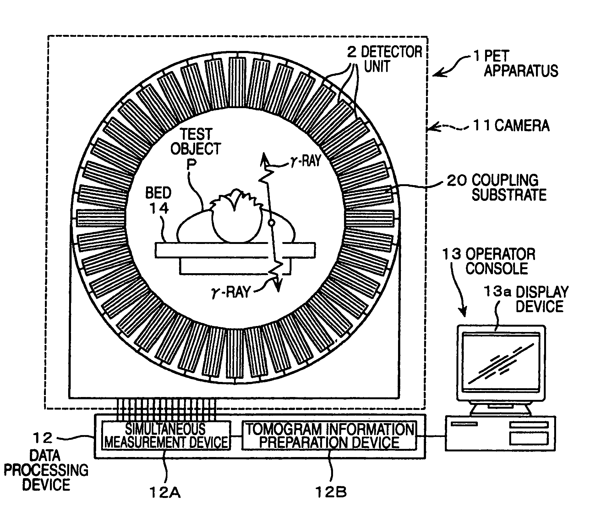
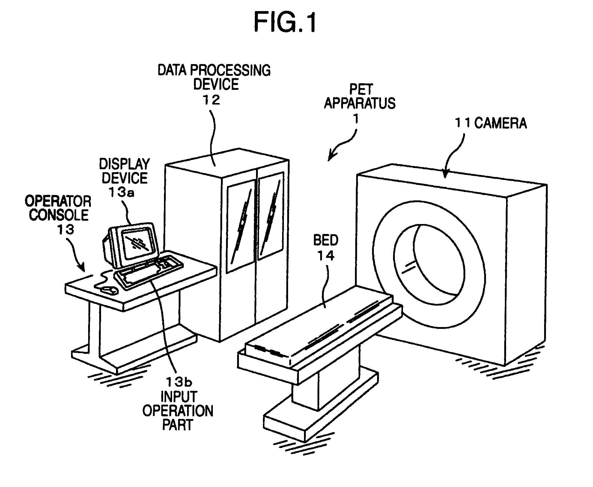
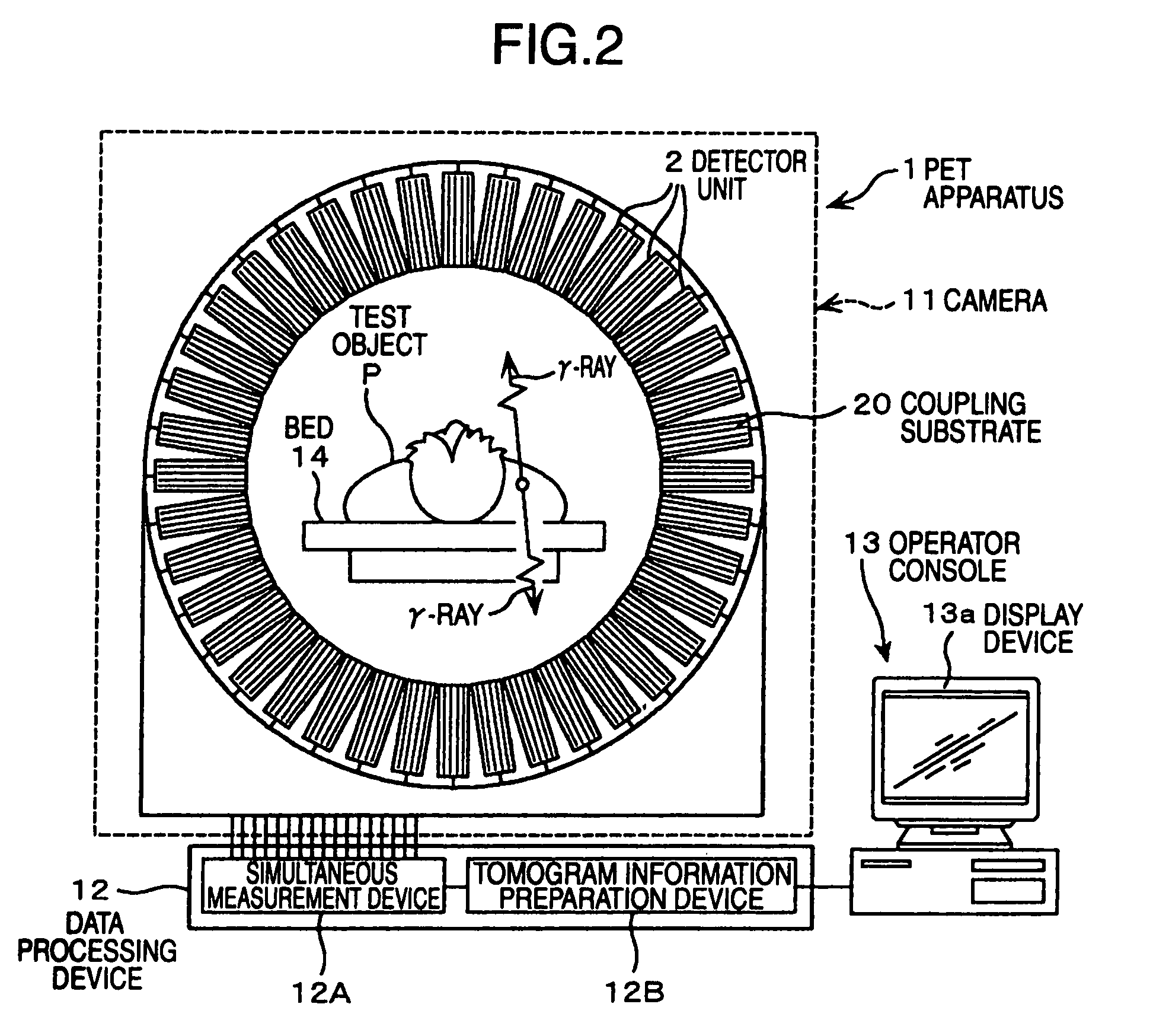
[0038]As shown in FIG. 1, a PET apparatus 1 as the nuclear medical diagnosis apparatus comprises a ca...

second embodiment

[0178]Next, a nuclear medical diagnosis apparatus, which is another embodiment concerning the present invention, will be described with reference to FIG. 17 to FIG. 20. The nuclear medical diagnosis apparatus of the present embodiment is a SPECT apparatus.

[0179]The same configuration as that of the first embodiment is given the same reference numeral to omit the duplicated description.

[0180]FIG. 17 is a perspective view showing the configuration of a SPECT apparatus, and FIG. 18 is a block diagram showing a connection relation between an analog ASIC and a digital ASIC in the SPECT apparatus. FIG. 19 is a functional block diagram of the analog ASIC, and FIG. 20 is a functional block diagram of the digital ASIC.

[0181]A SPECT apparatus 51 comprises a pair of radiation camera parts 52, a rotating support stand 57, a data processing device 58, and an operator console 13A. The radiation camera parts 52 are disposed facing to each other on the rotating support stand 57 at positions shifted...


PUM


Abstract

A PET apparatus comprises a plurality of detector units in the circumferential direction, wherein the detector unit includes a plurality of unit substrates therein, and wherein the unit substrate includes: a plurality of detectors upon which a γ-ray is incident; and an analog ASIC and digital ASIC for processing a γ-ray detection signal outputted by each of the detectors. The analog ASIC includes two slow systems having mutually different time constants, each of which outputs a pulseheight value. A noise determination part of the digital ASIC determines whether a relevant detection signal is an intended γ-ray detection signal or a noise based on a correlation between the pulseheight values, and a noise counting part counts the number of times of noise determination, and a detector output signal processing control part controls the signal processing with respect to an output signal from a relevant detector based on the count.

Description

BACKGROUND OF THE INVENTION[0001]The present invention relates to nuclear medical diagnosis apparatuses, and in particular relates to a positron emission computed tomography apparatus (hereinafter, referred to as a PET apparatus) that is one type of the nuclear medical diagnosis apparatuses using radiation detectors, a single photon emission computed tomography apparatus (hereinafter, referred to as a SPECT apparatus), and a γ-camera using γ-rays passing through a test object.[0002]Conventionally, as the radiation detectors for detecting radiation, such as γ-rays, a radiation detector using an NaI scintillator is known. In the γ-camera equipped with an NaI scintillator, radiation (γ-ray) is incident upon the NaI scintillator at an angle limited by a large number of collimators, thus interacting with an NaI crystal to emit scintillation light. This light reaches a photomultiplier or a photodiode via a light guide to become an electrical signal. The electrical signal is shaped by a me...

Claims


Application Information

Patent Timeline
Patent Type & Authority Patents(United States)
IPC IPC(8): G01T1/164
CPCG01T1/249G01T1/2018G01T1/20184G01T1/20188
Inventor TAKAHASHI, ISAOISHITSU, TAKAFUMIUENO, YUICHIROSEINO, TOMOYUKI
Owner HITACHI LTD
Learn More