Heating apparatus, and coating and developing apparatus

a technology of developing apparatus and heating apparatus, which is applied in lighting and heating apparatus, drying machines with progressive movements, instruments, etc., can solve the problems of increasing the amount of attachment, and affecting the effect of the surface coating coating, so as to reduce the overhead time, enhance the throughput, and eliminate the possibility of occurrence of warp errors in the carrying of the substrate.

Inactive Publication Date: 2010-09-21
TOKYO ELECTRON LTD
View PDF332 Cites 27 Cited by
  • Summary
  • Abstract
  • Description
  • Claims
  • Application Information

AI Technical Summary

Benefits of technology

[0014]The present invention was made in light of the above, and it is an object thereof to enhance the throughput by reducing the overhead time and / or reduce the amount of attachment of particles onto a substrate, in a heating apparatus including a cooling plate and a heating plate.
[0025]In the present invention described above, the substrate can be carried in the heating chamber having a flat space, while being held on the carrying means, and then be subjected to a heat treatment as it is. Also in the present invention, a cover which can be optionally raised and lowered is not provided to the heating chamber, and the action for transferring the substrate to the heating plate is unnecessary. Therefore, the action for raising and lowering the cover as well as the time required for transferring the substrate to the heating plate can be eliminated, thus the overhead time can be reduced in accordance with the time saving, thereby enhancing the throughput. In addition, since the heat treatment can be performed with the substrate being floated over the heating plates, even when the substrate is warped, the action for placing the warped substrate onto the heating plate becomes unnecessary. Thus, the possibility of occurrence of mistakes in carrying the substrate caused by its warp can be eliminated, thereby performing the heat treatment in a stable state.
[0026]Furthermore, since a cover which can be optionally raised and lowered is not provided in the heating chamber, there-is no possibility of occurrence of disturbance of the air current in the heating chamber to be caused by raising and lowering of such a cover. Accordingly, the air current in the heating apparatus becomes difficult to be disturbed, thereby reducing attachment of particles onto substrate to be caused by the occurrence of disturbance of the air current.

Problems solved by technology

Therefore, between the heating plate 12 and the top plate 18, a gap greater than 10 mm should be required to meet both of such a thickness of the cooling plate 13 and the clearance for transferring the wafer W. However, such a large gap between the heating plate 12 and the top plate 18 may promote the entering of an external air into the gap, causing disturbance of the air current, thus compromising a desired one-way air current.
Consequently, exhaustion of sublimates along a predetermined direction can not be performed satisfactorily, resulting in increase of the amount of attachment, onto the wafer W, of the sublimates produced from a resist liquid.
However, such raising and lowering motions of the top plate 18 may also disturb the air current in the interior of the heating apparatus.
Accordingly, the exhaustion of sublimates can not be achieved satisfactorily, also causing attachment of particles onto the wafer W.
However, this Patent Document 1 does not suppose that the carrying mechanism can be applied to a heating apparatus including a cooling plate and a heating plate, that control of disturbance of an air current in a heating apparatus can be utilized to reduce the amount of attachment of particles to the wafer W, and that a heat treatment can be performed while holding the wafer W in a floated state over the heating plate using an arm.

Method used


Image

  • Heating apparatus, and coating and developing apparatus
  • Heating apparatus, and coating and developing apparatus
  • Heating apparatus, and coating and developing apparatus

Examples


examples

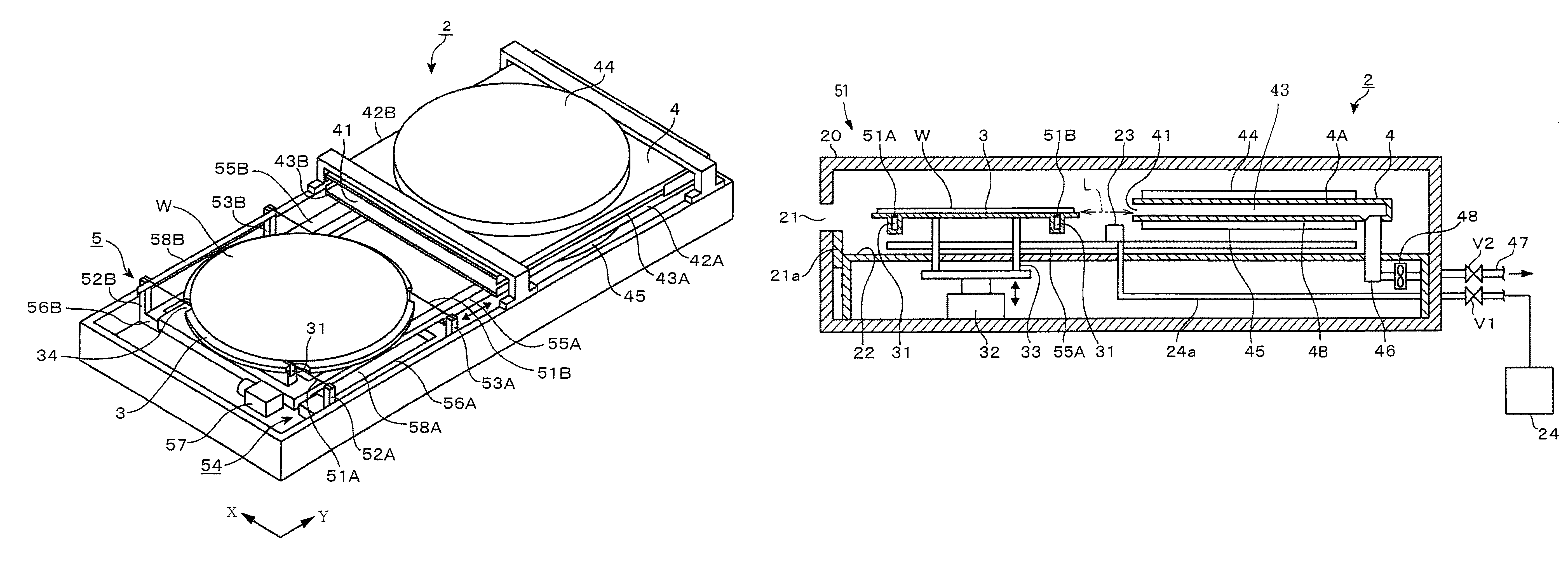
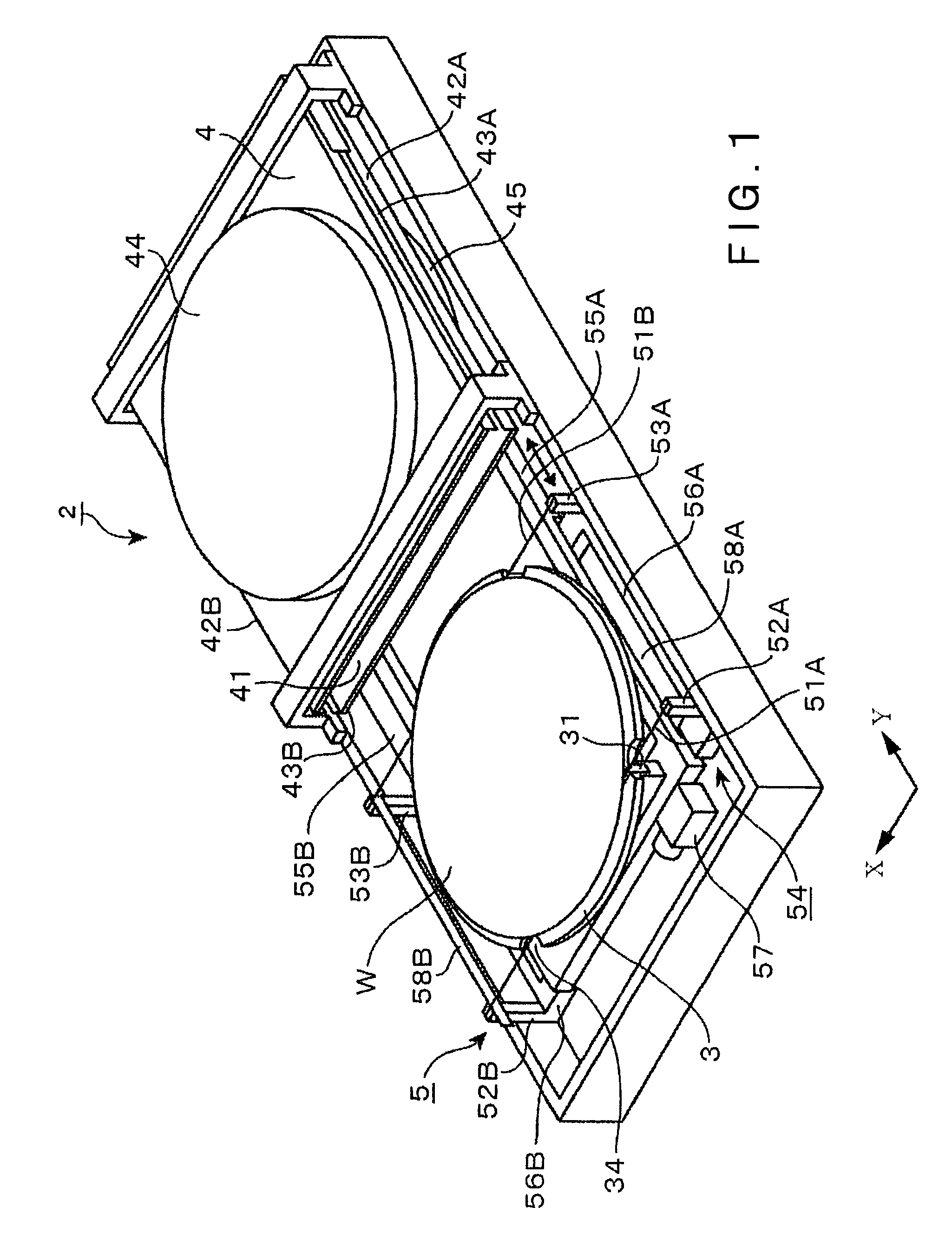
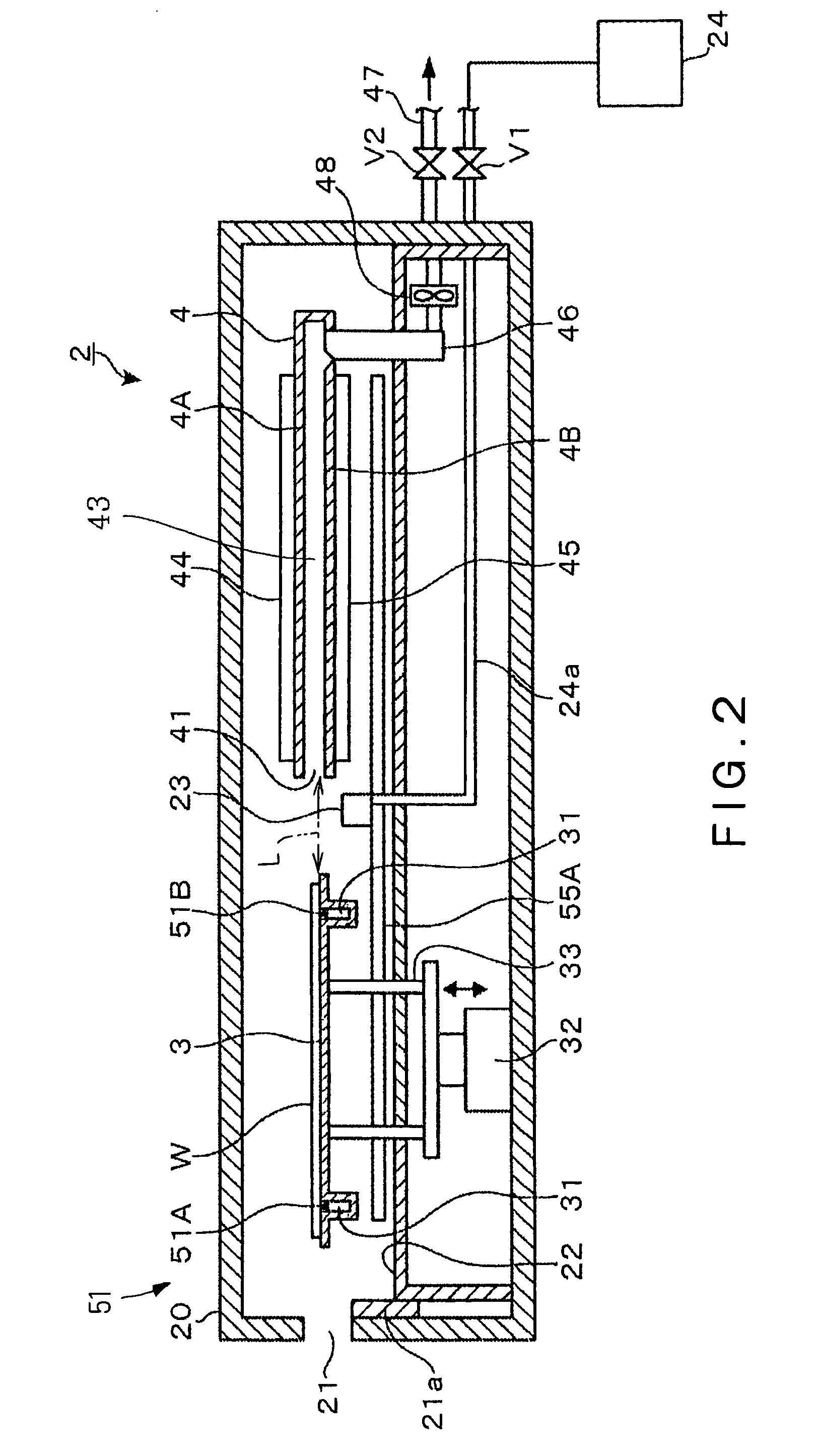
[0044]As one example of an embodiment of a heating apparatus according to the present invention, a heating apparatus 2 adapted to heat a wafer W, which is, for example, a substrate having a resist liquid as a coating liquid coated on its surface, so as to form a resist film on the surface of the wafer W will be described below with reference to FIGS. 1 to 7. In respect of the size of the wafer W, the water W having a size of 12 inches may be used, for example. The heating apparatus 2, as shown in FIG. 2, comprises a housing 20 constituting a treatment chamber. A carrying opening 21 for the wafer W is formed in a side wall of the housing 20 such that the carrying opening 21 can be optionally opened and closed by a shutter 21a. While the shutter 21a is provided to prevent disturbance of an air current to be formed around the wafer W as described below due to inflow of an external air into the housing 20 through the carrying opening 21, the inflow of an external air may also be prevent...


PUM


Abstract

A heating apparatus 2 comprises a housing 20; a flat heating chamber 4 which is provided in the housing 2 and adapted to heat a wafer W used as a substrate, with one side of the heating chamber 4 opening for carrying in and carrying out the wafer; and a heating plates 44, 45 provided in the heating chamber 4 such that the wafer W can be heated from both above and below. A cooling plate 3 is provided in the housing 20 located in the vicinity of the opening of the heating chamber 4, for cooling the wafer W after being heated by the heating plates 44, 45. Additionally, a carrying means is provided in the housing 20 for carrying the wafer W between an upper position of the cooling plate 3 and the interior of the heating chamber 4 such that a heat treatment for the wafer W can be performed with the wafer W being held in the heating chamber 4.

Description

BACKGROUND OF THE INVENTION[0001]1. Field of the Invention[0002]The present invention relates to a heating apparatus for heating a substrate on which a coating liquid has been coated, and a coating and developing apparatus including the heating apparatus.[0003]2. Background Art[0004]As an apparatus for forming a resist pattern on a glass substrate for use in a semiconductor wafer (hereinafter, referred to as “a wafer”) or an LCD (Liquid Crystal Display), a coating and developing apparatus is used, which coats a resist on the wafer and then develops the wafer after exposure. In this apparatus, a heating apparatus is incorporated, which is also referred to as a baking apparatus and serves to dry a solvent of a resist liquid, for example, in an apparatus for heating a wafer on which the resist liquid is coated.[0005]With such a heating apparatus, we have attempted to perform a heating treatment by forming an air current passage by covering a region above a heating plate for heating a w...

Claims


Application Information

Patent Timeline
Patent Type & Authority Patents(United States)
IPC IPC(8): F26B21/06
CPCC30B33/02C30B35/00H01L21/67098H01L21/67748G03F7/168G03F7/70733
Inventor FUKUOKA, TETSUOAKIMOTO, MASAMIKITANO, TAKAHIROKIMURA, YOSHIOHAYASHI, SHINICHIITO, HIKARU
Owner TOKYO ELECTRON LTD
Why Eureka
Try Eureka