Prosthesis for restoring motion in an appendage or spinal joint and an intervertebral spacer

a technology of appendage or spinal joint and prosthesis, which is applied in the direction of prosthesis, femoral head, other domestic objects, etc., can solve the problems of increasing the life expectancy of the artificial disc, stress shielding, and wear, and achieves less stiffness, reduce stress shielding, and enhance the life of the prosthesis

Active Publication Date: 2010-09-21
SEASPINE
View PDF55 Cites 135 Cited by
  • Summary
  • Abstract
  • Description
  • Claims
  • Application Information

AI Technical Summary

Benefits of technology

[0009]In a broad sense a motion restoring prosthesis adapted to be placed between the ends of two bones adjoining a mammalian appendage or spinal joint, in accordance with the present invention, includes two components with each component defining an outer surface for attachment to a respective bone end and an articulating surface for engaging the articulating surface of the other component. At least one of the components has an inner and outer section. The inner section, defining the articulating surface, is made of a primary relatively hard / stiff material such as ceramic, cobalt chromium, or other hard, stiff bio-compatible material for inhibiting the wear between the articulating surfaces. The outer section is made of a secondary material (sometimes hereinafter referred to as the “bone buttressing material”) that is softer and less stiff than the primary material (sometimes referred to as the “articulating material”). Preferably the secondary material is formed of a biocompatible polymer having a hardness / stiffness characteristic closer to that of the bone to be buttressed. Polyetheretherketone (“PEEK”) or carbon fiber reinforced PEEK (“CFRPEEK”) are clear choices. These polymers reduce stress shielding by more evenly distributing the forces or load from the articulating surfaces to the respective bone interface end thereby enhance the life of the prosthesis.
[0011]Optionally, the bone buttressing surface of each of the outer sections are roughened and / or made uneven to enhance the attachment of bone thereto. Further, it is desirable for the bone buttressing surface to have a very thin coating or layer of a bone-on growth attachment friendly material, such as titanium, calcium phosphate or hydroxyapatite thereon, which does not materially increase the stiffness of the bone buttressing surface of the secondary material to detract from the stress shielding characteristic thereof, while enhancing the attachment of the bone thereto. Preferably the thin coating of such material is within the range of about 0.5 to 15.0 or more microns and most preferably within the range of about 0.50 to 3.0 microns.
[0013]Again, it is preferable that the softer outer sections partially encapsulate the inner sections, e.g., by an injection molding process, to substantially prevent any motion including macromotion between the inner and outer sections.
[0014]With respect to item (b) an artificial intervertebral disc or spacer, for accommodating fusion, is preferably formed of a material such as PEEK or CRFPEEK having a flexure modulus comparable to that of cortical bone. The spacer is provided with a roughened and / or uneven surface and subsequently provided with a very thin coating of a material such as Ti which enhances bone-on growth without adversely affecting the bone friendly surface characteristic of the PEEK or CFRPEEK as discussed above.

Problems solved by technology

Both the Yuichiro and Gill et al. patents describe devices which rely on point contact, a potential source of excessive wear debris.
The use of a hard / stiff material, generally ceramic or a cobalt chromium alloy, to provide the articulating surfaces decreases the wear and increases the life expectancy of the artificial disc.
However, the use of the same material or rigid plates, as in the '437 patent, abutting the faces of the separated vertebrae, results in stress shielding, i.e., a nonuniform distribution of the forces transmitted from the articulating surfaces to the abutted vertebrae bone faces.
This nonuniform loading can result in so called hard spots on the bone face where the load is being transmitted and soft spots where little or no load is being transmitted, with the consequence that the soft spots tend to result in bone absorption, thereby loosening the implant and causing eventual failure.
Such wear, given time, will cause separation at the interface and shorten the useful life of the prosthesis.
The above problems are also associated with artificial limb replacement joints, except that some joint replacements such as hip joints may, as a practical matter, have a need to relieve the stress imparted only to one of the bone ends, e.g., the bone portion forming the acetabulum.
As discussed above, the metal to bone contact provides a nonuniform stress loading to the exposed bone face with a significant potential of causing the implant to loosen from the underlying implant.
However, the interface between the outer metal shell and the bone end or face forming the acetabulum does not resolve the nonuniform loading on the bone face.
However, PEEK is not particularly bone attachment friendly.

Method used


Image

  • Prosthesis for restoring motion in an appendage or spinal joint and an intervertebral spacer
  • Prosthesis for restoring motion in an appendage or spinal joint and an intervertebral spacer
  • Prosthesis for restoring motion in an appendage or spinal joint and an intervertebral spacer

Examples


Embodiment Construction

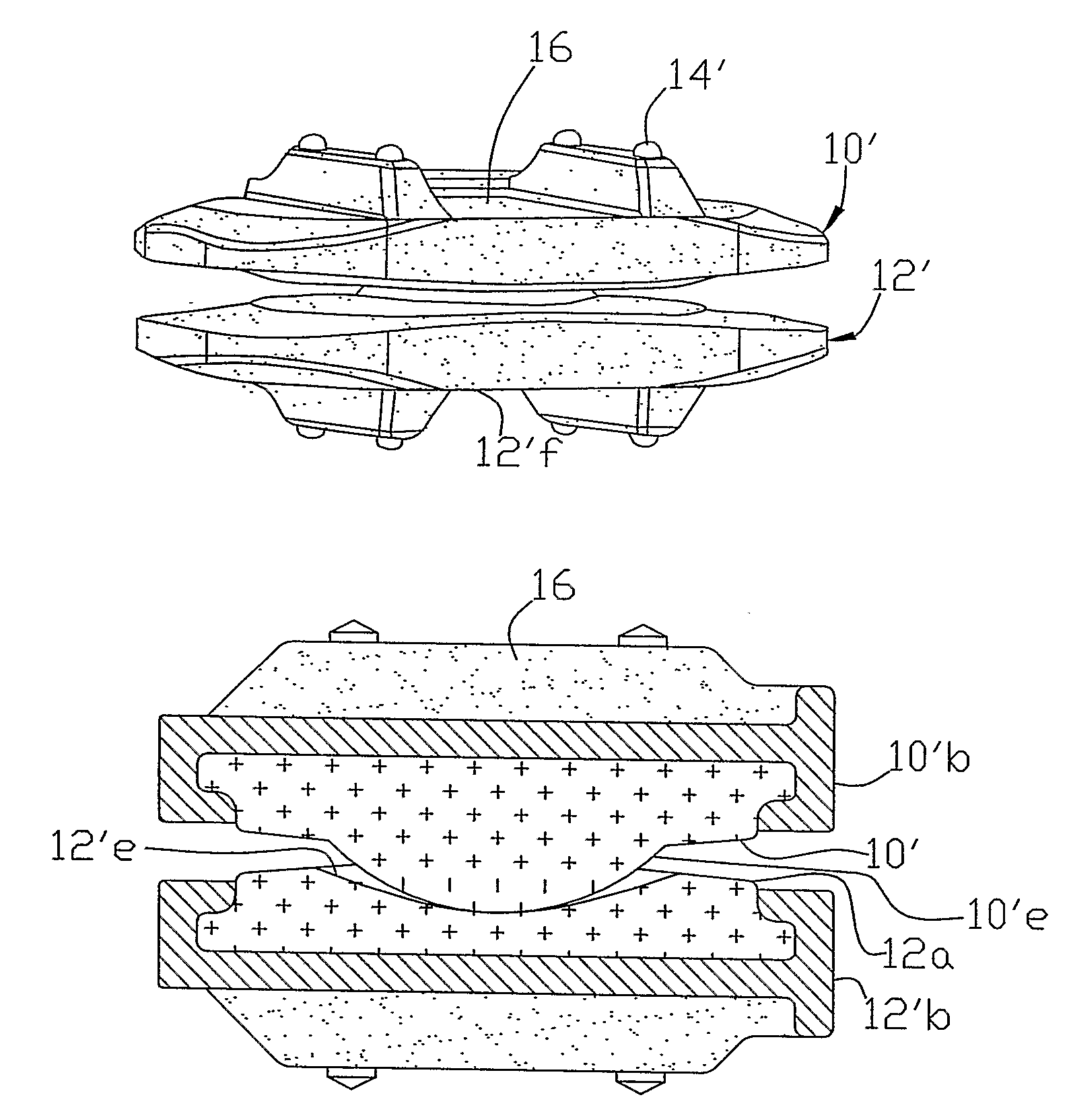
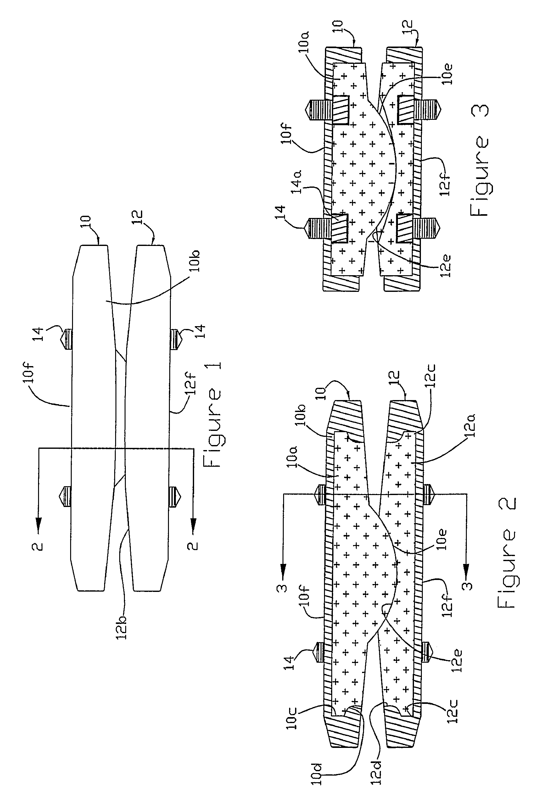
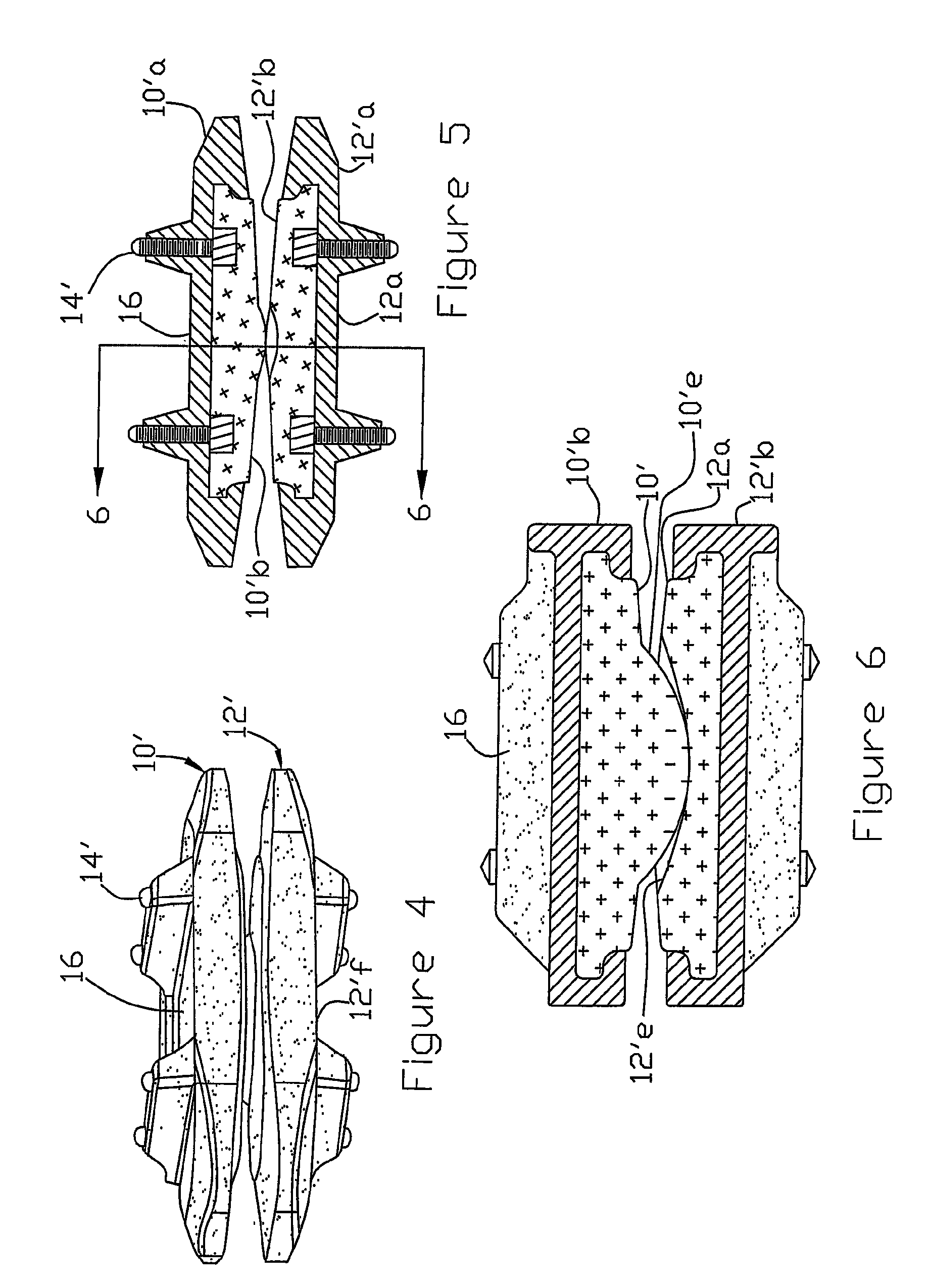
[0030]Referring now to FIGS. 1-3, a motion restoring intervertebral prosthesis, in accordance with this invention, comprises first and second components 10 and 12 with the components having inner sections 10a and 12a (formed of a primary material) and outer sections 10b and 12b (formed of a secondary material), respectively. The sections are integrally formed, preferably by an injection molding process, so that the secondary material partially encloses or encapsulates the primary material (except for the articulating surfaces) as will be explained with respect to FIG. 17. Briefly, outwardly extending protrusions 10c and 12c of the primary material are overlapped by an inwardly extending shoulders 10d and 12d of the secondary material. The inner sections 10a and 12a define cooperating articulating surfaces 10e and 12e in the form of a ball and modified socket to provide controlled rotation in the frontal plane and controlled rotation with translation in the sagittal plane as is descr...


PUM

PropertyMeasurementUnit
thicknessaaaaaaaaaa
thicknessaaaaaaaaaa
thicknessaaaaaaaaaa

Abstract

A motion restoring prosthesis to be interposed between the ends of two bones adjoining a mammalian appendage or spinal joint is formed of two components with the components having inner cooperating articulating surfaces and outer bone engaging surfaces. At least one of the components has an inner section made of relatively hard, stiff material defining one or the articulating surfaces and an outer section made of a softer material defining the bone engaging surface. The softer material having a hardness / stiffness characteristic compatible with the bone to reduce stress shielding and more evenly distribute the forces from the articulating surfaces to the associate bone interface.

Description

RELATED APPLICATION[0001]This application is based on and claims priority of U.S. Provisional Application No. 60 / 676,744 (“'744 application”) for a Motion Restoring Intervertebral Device filed on May 2, 2005, the contents of the provisional application are incorporated herein by reference.FIELD OF THE INVENTION[0002]This application relates to (a) motion restoring prosthesis for placement between the ends of two bones adjoining a mammalian appendage or spinal joint, such as an artificial intervertebral disc or hip / knee / shoulder joint and (b) intervertebral spacer for accommodating fusion between the separated vertebrae.BACKGROUND OF THE INVENTION[0003]With respect to motion restoring intervertebral devices see German Patent No. 2,263,842 and the devices disclosed therein. These include ball and socket prostheses with single and / or dual articulations and with and without motion dampening elements. The clinical use of the device containing a ball supported by two opposing sockets exte...

Claims


Application Information

Patent Timeline
Patent Type & Authority Patents(United States)
IPC IPC(8): A61F2/44
CPCA61F2/34A61F2/4425A61F2/4465A61L27/18A61L27/306A61L27/32B29C45/14B29C45/14434B29C45/14778C08L71/12A61F2/30767A61F2/3094A61F2/30965A61F2/32A61F2/36A61F2/3662A61F2002/30014A61F2002/30118A61F2002/30133A61F2002/30685A61F2002/30787A61F2002/30822A61F2002/30827A61F2002/30841A61F2002/30892A61F2002/30904A61F2002/30906A61F2002/30957A61F2002/30971A61F2002/30973A61F2002/3611A61F2002/3625A61F2002/4475A61F2230/0006A61F2230/0015A61F2250/0018A61F2310/00029A61F2310/00179A61F2310/00203A61F2310/00407A61F2310/00796B29C45/34B29K2071/00B29L2031/7532A61F2002/30593C08L71/00
Inventor SMITH, COLIN M.CORDARO, NICHOLAS M.
Owner SEASPINE
Why Eureka
Try Eureka