Light-emitting device

a technology of light-emitting devices and light-emitting tubes, which is applied in the direction of semiconductor devices for light sources, lighting and heating apparatus, and light-emitting support devices. it can solve the problems of increasing the heat resistance of the sapphire substrate, difficult to increase the power of the light output, and inability to produce the desired light output by only one white led. it can prolong the creepage distance and enhance the protection of the surge protection

Active Publication Date: 2010-09-21
PANASONIC CORP
View PDF21 Cites 51 Cited by
  • Summary
  • Abstract
  • Description
  • Claims
  • Application Information

AI Technical Summary

Benefits of technology

[0009]The present invention was made in view of above situation, and the object of the present invention is to provide a light-emitting device which can constrain an increase in temperature of an LED chip and can increase a power of the light output.

Problems solved by technology

Also, the application of white LEDs to a luminaire has become an active area for research and development in accordance with recent high output of white LEDs, but when the white LED is applied to an application which requires a relatively high light output such as general illumination, a desired light output cannot be produced by only one white LED.
Therefore, it is necessary to limit the input power to each LED chip 10′ to prevent the junction temperature of each LED chip 10′ from rising above the maximum junction temperature, so it is difficult to increase the power of the light output.
Therefore, when the sapphire substrate, that is the substrate for crystal growth, is mounted on the metal plate 201 to be thermally connected, there is a problem that the heat resistance of the sapphire substrate is increased.

Method used


Image

  • Light-emitting device
  • Light-emitting device
  • Light-emitting device

Examples


first embodiment

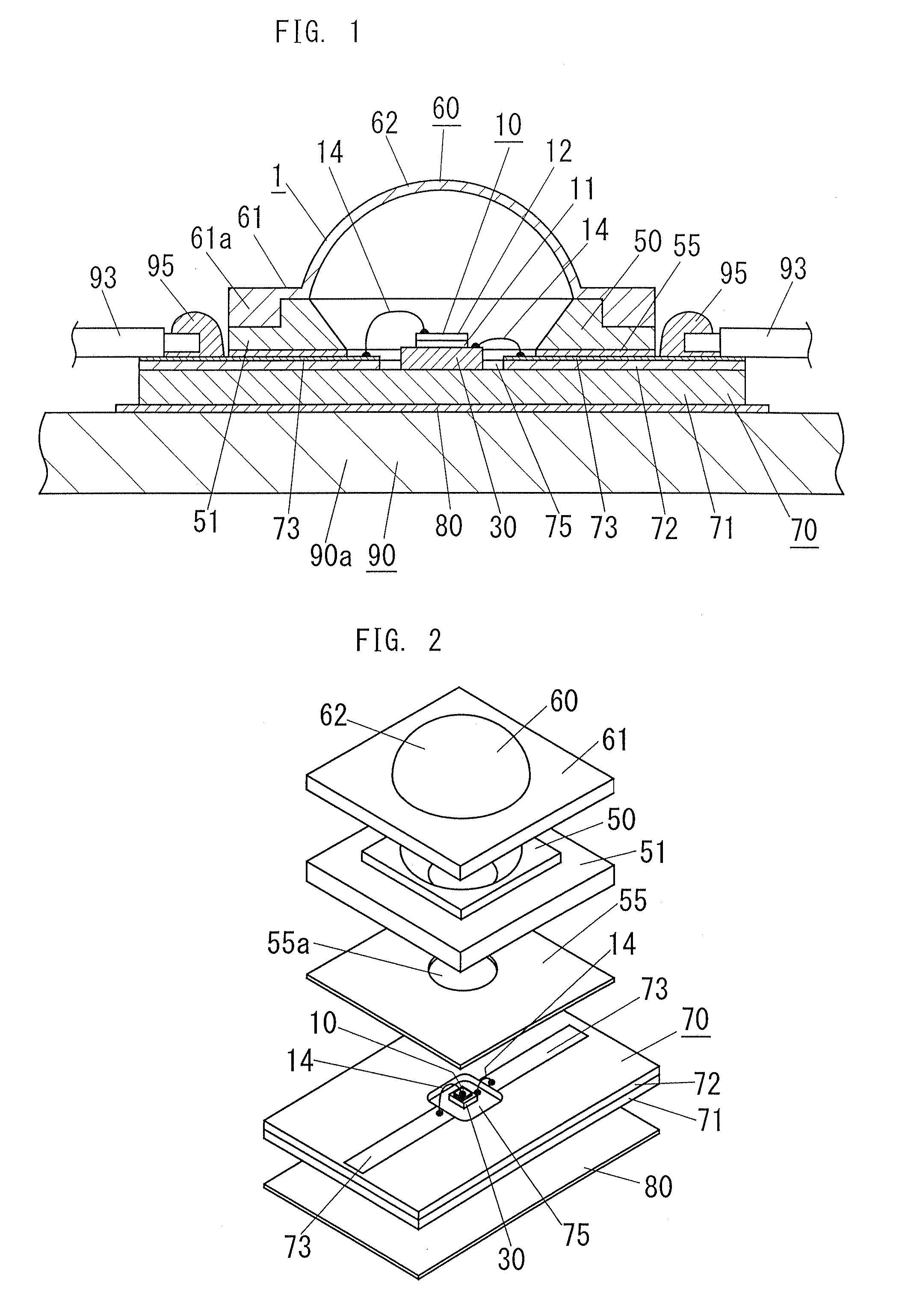
[0033]Hereinafter, a light-emitting device of the present embodiment will be explained with reference to FIG. 1 to FIG. 4.

[0034]A light-emitting device (LED chip unit) 1 of the present embodiment is used as a light source of a luminaire, and includes: an LED chip 10 in a form of a rectangular plate, a chip mounting member 70, a sub-mount member 30, a reflector (reflecting device) 50, a protective cover 60, and a sheet-shaped connecting member 80. The chip mounting member 70 has a conductive plate 71 in a form of a rectangular plate and conductor patterns (lead patterns) 73, 73. The conductive plate 71 is formed to have a chip size larger than that of the LED chip 10, and the LED chip 10 is mounted to one surface side of the conductive plate 71. The conductor patterns 73, 73 are formed on the one surface side of the conductive plate 71 through an insulating part 72 and electrically connected to the LED chip 10. The sub-mount member 30 is disposed between the conductive plate 71 and t...

second embodiment

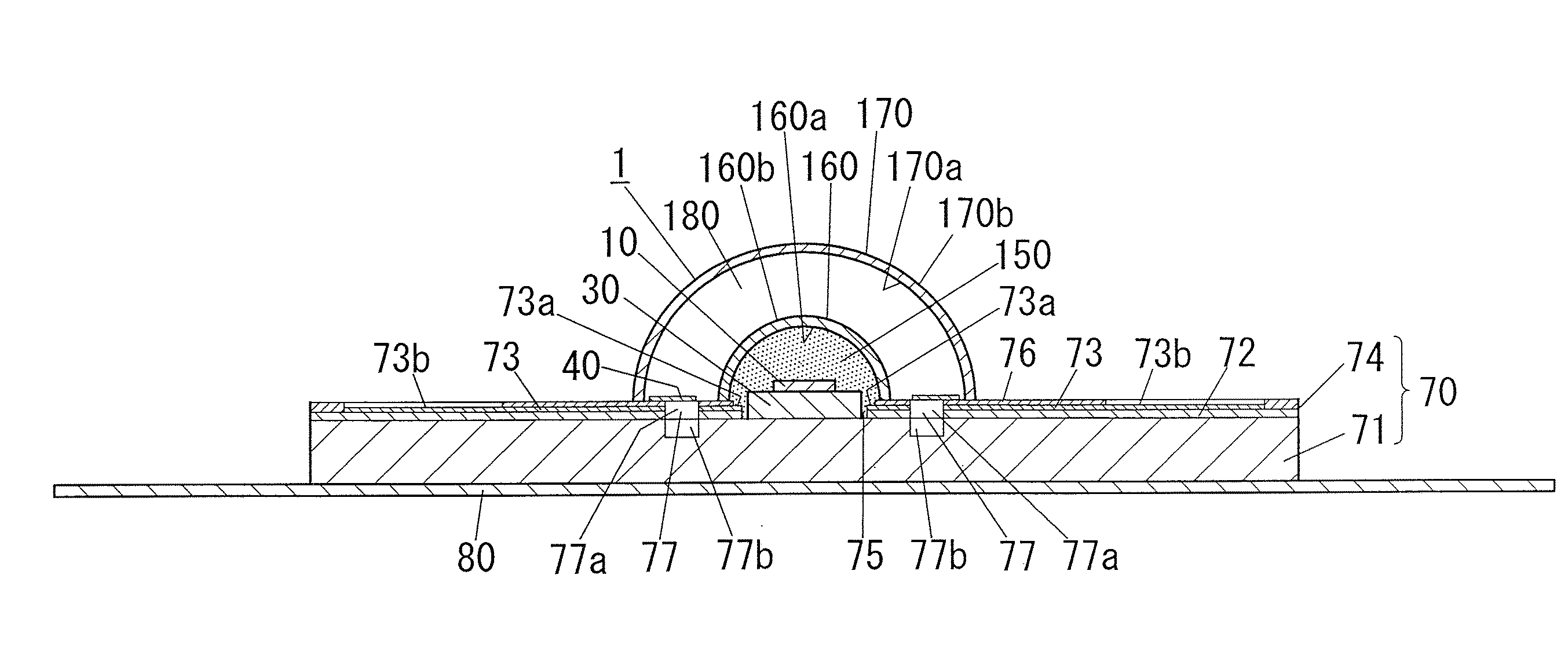
[0060]Hereinafter, a light-emitting device of this embodiment will be explained with reference to FIG. 5 to FIG. 11.

[0061]The light-emitting device 1 of the present embodiment is generally configured in the same manner as that of the first embodiment, but unlike the first embodiment, it includes a dome-shaped optical member 160, a sealing part 150, and a dome-shaped color converting member 170. The dome-shaped optical member 160 controls the distribution of light emitted from the LED chip 10, and it is made of a translucent material, and is fixedly attached to one surface side (the upper surface side in FIG. 5) of the chip mounting member 70 in such a way that the LED chip 10 is housed between the dome-shaped optical member 160 and the chip mounting member 70. The sealing part 150 is made of an encapsulation resin and has a translucency and an elasticity, and it seals the LED chip 10 and a plurality of (four in this embodiment) bonding wires 14 that are electrically connected to the...


PUM


Abstract

A light-emitting device of the present invention includes: a LED chip 10; a chip mounting member 70 having a conductive plate (heat transfer plate) 71 one surface side of which the LED chip 10 is mounted on and a conductor patterns 73, 73 which is formed on the one surface side of the conductive plate 71 through an insulating part 72 and electrically connected to the LED chip 10; and a sheet-shaped connecting member 80 disposed on the other surface side of the conductive plate 71 to connect the conductive plate 71 to a body of the luminaire 90 which is a metal member for holding the chip mounting member 70. The connecting member 80 is made of a resin sheet which includes a filler and whose viscosity is reduced by heating, and the connecting member 80 has an electrical insulating property and thermally connects the conductive plate 71 and the body 90 of the luminaire to each other.

Description

TECHNICAL FIELD[0001]The present invention relates to a light-emitting device.BACKGROUND ART[0002]Conventionally, light-emitting devices which emits light having a different color from the emission color of a LED chip by combining the LED chip and a phosphor (e.g., fluorescent pigment and fluorescence dye) as a wavelength converting material which emits light having an emission color different from that of the LED chip when excited by the light emitted by the LED chip have been researched and developed at various places. Such light-emitting devices include a commercialized white light-emitting device (which is generally called a white LED) in which an LED chip for emitting blue light or ultraviolet light is combined with a phosphor to produce a white light (emission spectrum of white light).[0003]Also, the application of white LEDs to a luminaire has become an active area for research and development in accordance with recent high output of white LEDs, but when the white LED is appl...

Claims


Application Information

Patent Timeline
Patent Type & Authority Patents(United States)
IPC IPC(8): H01L33/00H01L33/48H01L33/58H01L33/62H01L33/64
CPCF21K9/00H01L33/483H01L33/58H01L33/62H01L33/64H01L2224/48091H01L2224/73265F21V21/30F21Y2105/00F21Y2115/10H01L2924/00014
Inventor URANO, YOUJINAKATANI, TAKUYAHIDAKA, YASUHIRO
Owner PANASONIC CORP
Why Eureka
Try Eureka