Method and plant for producing low-temperature coke

a low-temperature coke and coke technology, applied in the direction of thermal non-catalytic cracking, special form destructive distillation, combustion process, etc., can solve the problems of dust-laden exhaust gas, e.g. from product cooling, unable to be integrated in the process, and restricted in terms of retention time, so as to achieve good energy utilization and perform more efficiently

Inactive Publication Date: 2010-09-28
OUTOTEC OYJ
View PDF116 Cites 7 Cited by
  • Summary
  • Abstract
  • Description
  • Claims
  • Application Information

AI Technical Summary

Benefits of technology

[0005]Therefore, it is the object of the present invention to provide a method for producing low-temperature coke, which can be performed more efficiently and is characterized in particular by a good utilization of energy.
[0008]As a result of the reduction of the flow velocity of the first gas or gas mixture upon leaving the central tube and / or as a result of the impingement on one of the reactor walls, a large part of the solids is precipitated from the suspension in the mixing chamber and falls back into the stationary annular fluidized bed, whereas only a small amount of non-precipitated solids is discharged from the mixing chamber together with the first gas or gas mixture. Thus, a solids circulation is obtained between the reactor regions of the stationary annular fluidized bed and the mixing chamber. Due to the sufficient retention time on the one hand and the good mass and heat transfer on the other hand, a good utilization of the thermal energy introduced into the low-temperature carbonization reactor and an excellent product quality is thus obtained. Another advantage of the method of the invention consists in the possibility of operating the process under partial load without a loss in product quality.
[0024]In accordance with a development of the invention it is proposed to heat the iron ore in the suspension heat exchanger by means of exhaust gas from a cyclone downstream of the reactor. In this way, the total energy demand of the process is further reduced.
[0030]To provide for a reliable fluidization of the solids and the formation of a stationary fluidized bed, a gas distributor is provided in the annular chamber of the low-temperature carbonization reactor, which divides the chamber into an upper annular fluidized bed and a lower gas distributor, the gas distributor being connected with a supply conduit for fluidizing gas and / or gaseous fuel. The gas distributor can constitute a gas distributor chamber or a gas distributor composed of tubes and / or nozzles, where part of the nozzles can each be connected to a gas supply for fluidizing gas and another part of the nozzles can be connected to a separate gas supply of gaseous fuel.
[0032]In the annular fluidized bed and / or the mixing chamber of the reactor, means for deflecting the solid and / or fluid flows can be provided in accordance with the invention. It is for instance possible to position an annular weir, whose diameter lies between that of the central tube and that of the reactor wall, in the annular fluidized bed such that the upper edge of the weir protrudes beyond the solids level obtained during operation, whereas the lower edge of the weir is arranged at a distance from the gas distributor or the like. Thus, solids separated out of the mixing chamber in the vicinity of the reactor wall must first pass by the weir at the lower edge thereof, before they can be entrained by the gas flow of the central tube back into the mixing chamber. In this way, an exchange of solids is enforced in the annular fluidized bed, so that a more uniform retention time of the solids in the annular fluidized bed is obtained.

Problems solved by technology

In the case of the stationary fluidized bed, this is chiefly due to the fact that although very long solids retention times are adjustable, the mass and heat transfer is rather moderate due to the comparatively low degree of fluidization, and dust-laden exhaust gas, e.g. from the product cooling, can hardly be integrated in the process.
Circulating fluidized beds, on the other hand, have better mass and heat transfer conditions due to the higher degree of fluidization, but are restricted in terms of their retention time because of this higher degree of fluidization.

Method used


Image

  • Method and plant for producing low-temperature coke
  • Method and plant for producing low-temperature coke
  • Method and plant for producing low-temperature coke

Examples


example 1

Low-temperature Carbonization without Addition of Ore

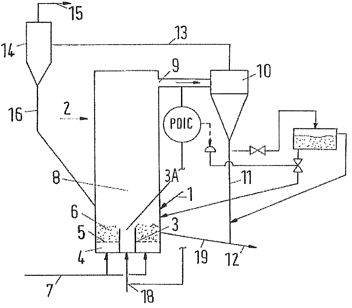
[0047]In a plant corresponding to FIG. 1, 128 t / h coal with a grain size of less than 10 mm with 25.4 wt-% volatile components and 16 wt-% moisture was supplied to the low-temperature carbonization reactor 2 via conduit 1.

[0048]Through conduits 18 and 7, 68,000 Nm3 / h air were introduced into the reactor 2, which air was distributed over conduit 18 and conduit 7 (fluidizing gas) in a ratio of 0.74:0.26. The temperature in the low-temperature carbonization reactor 2 was 900° C.

[0049]From the reactor 2, 64 t / h low-temperature coke were withdrawn via conduit 12, which coke consisted of 88 wt-% char and 12 wt-% ash. Furthermore, 157,000 Nm3 / h process gas with a temperature of 900° C. were withdrawn via conduit 15, which process gas had the following composition:

[0050]

11vol-% CO10vol-% CO224vol-% H2O20vol-% H21vol-% CH434vol-% N2.

example 2

Low-temperature Carbonization with Preheating of Ore

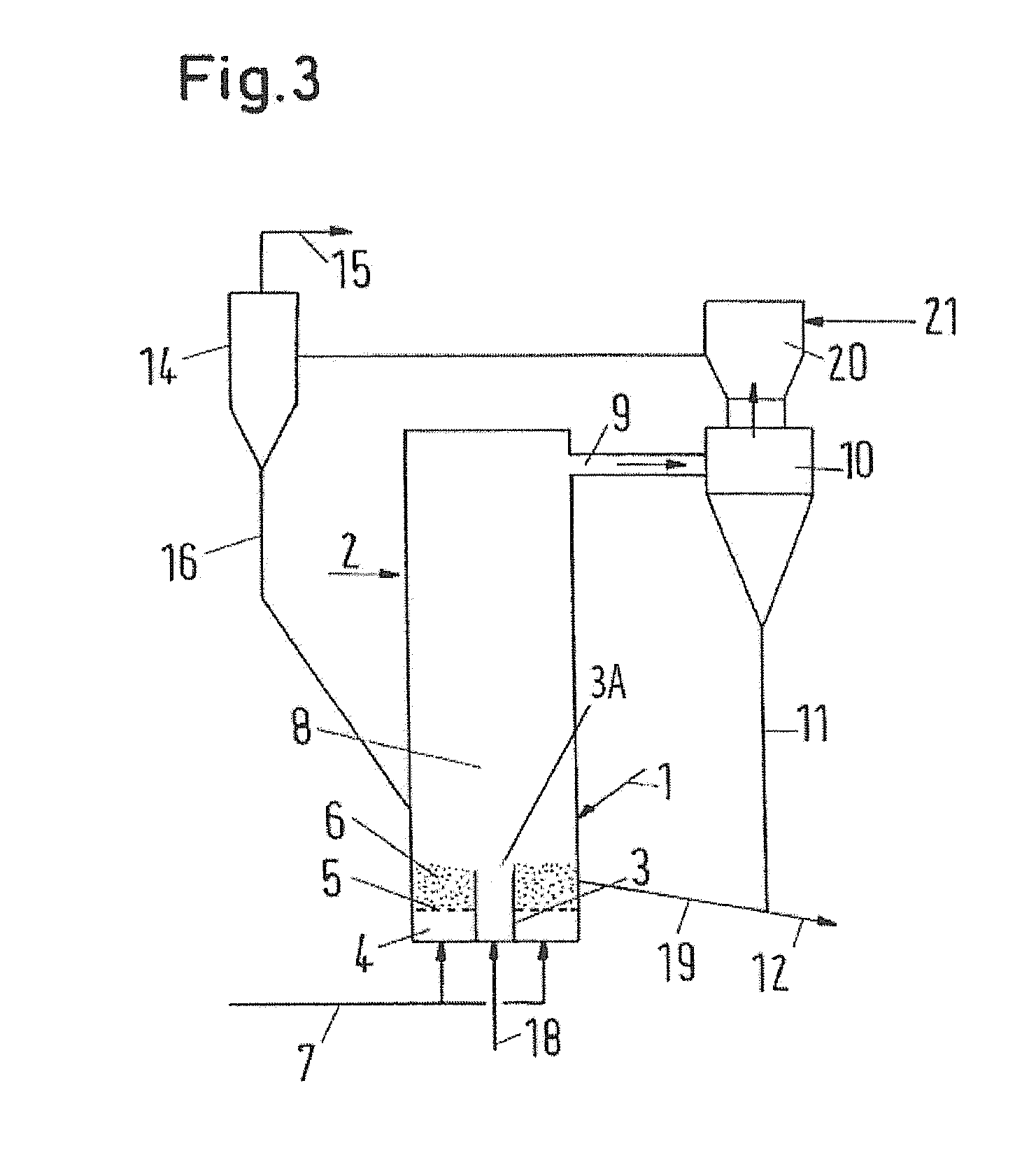
[0051]In a plant corresponding to FIG. 3, 170 t / h iron ore were supplied to the suspension heat exchanger 20 via conduit 21 and upon separating gas in the cyclone 14 charged into the low-temperature carbonization reactor 2 via conduit 16. Furthermore, 170 t / h granular coal with 25.4 wt-% volatile constituents and 17 wt-% moisture were supplied to the reactor 2 via conduit 1.

[0052]Via conduits 18 and 7, 114,000 Nm3 / h air were introduced into the reactor 2, which air was distributed over conduits 18 and 7 (fluidizing gas) in a ratio of 0.97:0.03. The temperature in the low-temperature carbonization reactor 2 was adjusted to 950° C.

[0053]From the reactor 2, 210 t / h of a mixture of low-temperature coke and iron ore were withdrawn via conduit 12, which mixture consisted of

[0054]

16wt-% Fe2O349wt-% FeO28wt-% char, and7wt-% ash.

[0055]Furthermore, 225,000 Nm3 / h process gas with a temperature of 518° C. were withdrawn from the plant via cond...


PUM

PropertyMeasurementUnit
temperatureaaaaaaaaaa
grain sizeaaaaaaaaaa
pressureaaaaaaaaaa

Abstract

The present invention relates to a method and a plant for producing low 15 temperature coke, in which granular coal and possibly further solids are heated to a temperature of 700 to 1050° C. in a fluidized-bed reactor (2) by means of an oxygen-containing gas. To improve the utilization of energy it is proposed to introduce a first gas or gas mixture from below through at least one gas supply tube (3) into a mixing chamber region (8) of the reactor (2), the gas supply tube (3) being at least partly surrounded by a stationary annular fluidized bed (6) which is fluidized by supplying fluidizing gas. The gas velocities of the first gas or gas mixture and of the fluidizing gas for the annular fluidized bed (6) are adjusted such that the Particle-Froude-Numbers in the gas supply tube (3) are between 1 and 100, in the annular fluidized bed (6) between 0.02 and 2 and in the 25 mixing chamber (8) between 0.3 and 30.

Description

[0001]This application claims the benefit of International Application No. PCT / EP2003 / 013501 filed on Dec. 1, 2003 under 35 U.S.C. §371, entitled, “Method and Plant for Producing Low-Temperature Coke” which claims the benefit of German Patent Application No. 102 60 734.6 filed on Dec. 23, 2002.TECHNICAL FIELD[0002]The present invention relates to a method for producing low-temperature coke, in which granular coal and possibly further solids are heated to a temperature of 700 to 1050° C. in a fluidized-bed reactor by means of an oxygen-containing gas, and to a corresponding plant.[0003]Such methods and plants are used for instance for producing low-temperature coke or for producing a mixture of low-temperature coke and ores, for instance iron ores. In the latter case, granular ore is supplied to the low-temperature carbonization reactor apart from granular coal. The low-temperature coke produced in this way, or the mixture of low-temperature coke and ore, can then be processed for in...

Claims


Application Information

Patent Timeline
Patent Type & Authority Patents(United States)
IPC IPC(8): C10G9/14B01J8/18C10B49/10C10B53/04
CPCC10B49/10C10B53/04
Inventor ORTH, ANDREASHIRSCH, MARTINWEBER, PETER
Owner OUTOTEC OYJ
Why Eureka
Try Eureka