Pulse generator circuit and communication apparatus

a generator circuit and circuit technology, applied in the direction of generating/distributing signals, pulse techniques, instruments, etc., can solve the problems of difficult configuration and limited performance of generated fine pulses, and achieve high reliability, high-sensitivity, and low cost

Active Publication Date: 2010-09-28
138 EAST LCD ADVANCEMENTS LTD
View PDF5 Cites 2 Cited by
  • Summary
  • Abstract
  • Description
  • Claims
  • Application Information

AI Technical Summary

Benefits of technology

[0015]According to the above configuration, the envelope of the output pulses is the output waveform generated by the first or second filter circuit, and the output pulses can be band-limited. In such a configuration, the band-limiting filter circuit can be a lowpass filter. Additionally, the frequency handled by the lowpass filter is approximately one-half the reciprocal of the pulse duration, and much lower than the central frequency of the output pulses. The above configuration does not require a bandpass filter that handles a high operating frequency band centered around the central frequency of the output pulses, unlike the band limitation in related art. Therefore, the configuration is simple and provides stable, accurate pulses.Second Application
[0017]According to the above configuration, it is possible to supply a circuit that can be readily configured in a semiconductor integrated circuit.Third Application
[0019]According to the above configuration, it is possible to supply a circuit that can be readily configured in a semiconductor integrated circuit. It is further possible to repeatedly use a logic circuit that evaluates a logic function using the n signals and the switching circuit, whereby the pulse generator circuit can be formed of a reduced number of devices even when a long pulse train is generated.Fourth Application
[0021]According to the above configuration, each of the first and second variable impedance circuits can be comprised of a transistor, and hence can be readily comprised of an integrated circuit, advantageously resulting in size reduction, high reliability, and cost reduction of the apparatus.Fifth Application
[0023]According to the above configuration, significantly fine, accurate pulses specific to UWB can be readily generated. Therefore, using the pulse generator circuit as a template generator circuit in a modulation circuit or a demodulation circuit allows a stable circuit system to be employed and a stable, highly-reliable, highly-sensitive apparatus to be configured at a low cost. Further, the present pulse generator circuit can generate high-frequency, accurate pulses close to the performance limit of the devices. The present configuration is therefore quite useful. Moreover, the present pulse generator circuit can be formed in a CMOS integrated circuit or any other suitable circuit, and can generate an accurate pulse waveform in a simple circuit even when the pulse waveform is formed of fine pulses on the order of the operating transition period of the devices. Further, since the present pulse generator circuit can be configured by a logic circuit using a CMOS integrated circuit, the pulse generator circuit can readily operate at the highest speed of the CMOS integrated circuit without increase in operating power. It is therefore possible to readily generate high-frequency, wideband pulses useable in UWB communication.

Problems solved by technology

The pulse generator circuit of the related art described above having a simple circuit configuration can accurately generate ultra-high-frequency, ultra-wideband pulses necessary for UWB communication, and the generated fine pulses are substantially circuit constituent device performance limited.
A problem with the filter is that the filter should be a bandpass filter that works at an ultra-wideband, ultra-high frequency that is close to the device performance limit and has good skirt characteristics and such a configuration is not easy to achieve.

Method used


Image

  • Pulse generator circuit and communication apparatus
  • Pulse generator circuit and communication apparatus
  • Pulse generator circuit and communication apparatus

Examples


first embodiment

Configuration of Pulses to be Generated

[0042]Pulses to be generated in the present embodiment will first be described with reference to FIGS. 9A-9G to FIG. 15. The pulses to be generated are single-ended output pulses shown in FIGS. 9E and 9F, or a pair of band-limited pulses having phases different from each other by 180 degrees shown in FIG. 9G. The waveform of the band-limited pulses will be described later in more detail with reference to FIGS. 10 to 15. FIG. 9G shows differential output pulse signals, and the potential difference between the outputs is equal to the waveform shown in FIG. 9E. Looking at the output potential difference as the differential signals, one can set the DC level during the no-pulse period indicated by ts shown in FIG. 9G to an arbitrary value as long as it is fixed.

[0043]The present embodiment will be described with reference to, by way of example, generation of the waveform having the following specifications, which are readily achievable by using mini...

second embodiment

[0082]A second embodiment of the pulse generator circuit will be described below with reference to FIGS. 3 and 4.

[0083]FIG. 3 is a circuit diagram showing the configuration of a pulse generator circuit 300 according to the second embodiment. FIG. 4 is a timing chart showing the operation of the pulse generator circuit 300 according to the second embodiment.

[0084]In FIG. 3, each of NOR circuits 303, 304, and 305 is an NOR-logic delay circuit. Let Q1, Q2, and Q3 be the outputs from the NOR circuits 303, 304, and 305. One of the two input terminals of each of the NOR circuits 303, 304, and 305 is connected to the corresponding one of the outputs Q3, Q1, and Q2 from the NOR circuits 305, 303, and 304 so as to form a ring oscillator circuit. Let C1, C2, and C3 be the other input terminals 308, 307, and 306 of the NOR circuits 303, 304, and 305.

[0085]When (Q1+Q2)×(Q3+Q1)×(Q2+Q3) is false, a pulse output terminal Pout 330 of a switching circuit 340 is connected to a power supply of a volta...

third embodiment

[0104]A third embodiment of the pulse generator circuit will be described below.

[0105]FIGS. 5 to 8 explain key portions of a communication apparatus using the pulse generator circuit 1 of the first embodiment or the pulse generator circuit 300 of the second embodiment, and show cases where the pulse generator circuit 1 or the pulse generator circuit 300 is applied to a UWB transmitter and a UWB receiver.

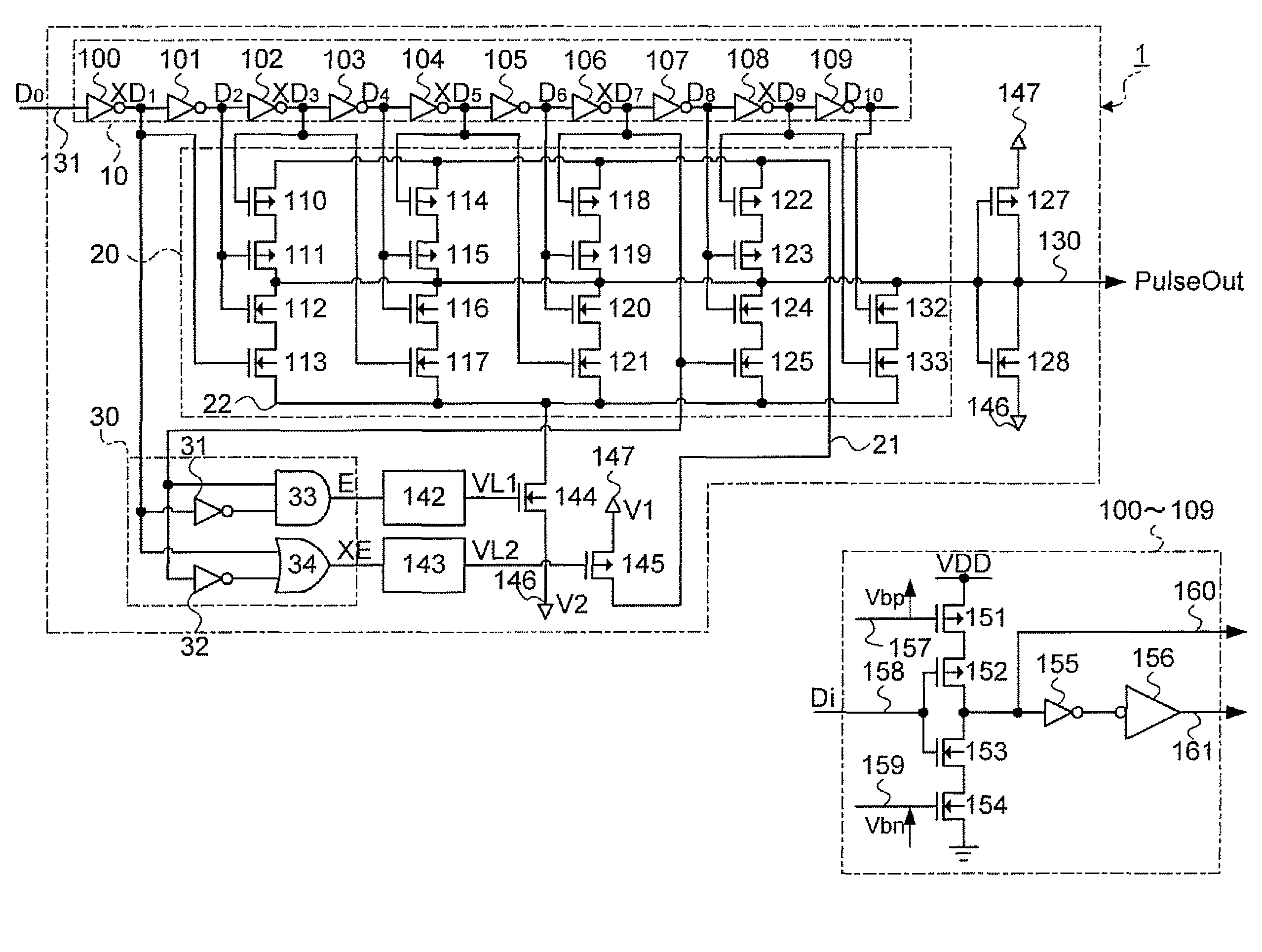
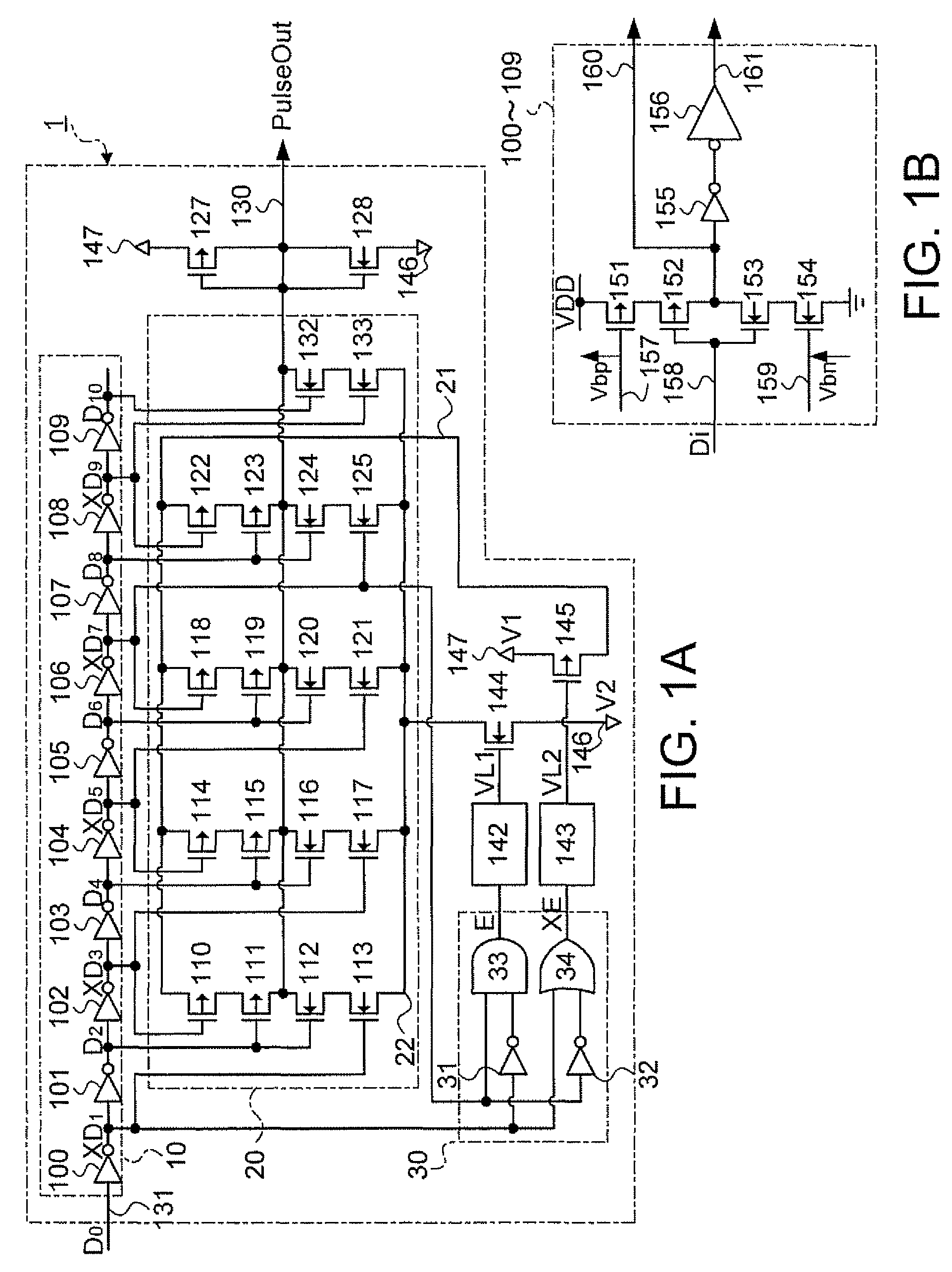
[0106]FIG. 5 is a block diagram schematically showing a UWB-IR transmitter 500. A pulse generator circuit 501 is comprised of the pulse generator circuit 1 (FIG. 1A) or the pulse generator circuit 300 (FIG. 3). An input terminal 503 is a terminal to which a start signal is inputted, and an input terminal 504 is a terminal to which data to be transmitted are inputted. The generated pulses are modulated in accordance with the signal inputted to the input terminal 504, and the modulation method will be described later. The thus generated pulses are transmitted via an antenna 502.

[0107]E...


PUM


Abstract

A pulse generator circuit that outputs pulses having a predetermined shape from an output terminal based on a start signal includes a timing generator circuit that generates (n) signals (n is an integer greater than or equal to 2), a pulse width signal generator circuit that generates a first pulse width signal and a second pulse width signal a first filter circuit limiting the band of the first pulse width signal, a second filter circuit limiting the band of the second pulse width signal, first and second power supplies, a first variable impedance circuit controlled by the first filter circuit, a second variable impedance circuit controlled by the second filter circuit, and a switching circuit that alternately connects the output terminal to the first power supply using a logic function value based on at least part of the n signals.

Description

BACKGROUND[0001]1. Technical Field[0002]The present invention relates to a pulse generator circuit that generates pulses suitable for UWB (Ultra Wide Band) communication, and also relates to a communication apparatus.[0003]2. Related Art[0004]UWB communication is a high-speed, large-capacity data communication method using an ultra-wide frequency band. Other examples of the communication method using a wideband signal include conventional spectrum spreading and orthogonal frequency division multiplexing (OFDM). On the other hand, UWB is a wider band communication method using ultra-short pulses, and also called an impulse radio (IR) communication, which is hereinafter referred to as a UWB-IR method or simply referred to as an IR method. In the IR method, only time-base operation, which is not based on conventional modulation, allows modulation and demodulation, and it is expected that the circuitry is simplified and the power consumption is reduced (see U.S. Pat. No. 6,421,389, Unit...

Claims


Application Information

Patent Timeline
Patent Type & Authority Patents(United States)
IPC IPC(8): G06F1/04
CPCH03K3/80H04B1/7172H04B1/7174
Inventor IKEDA, MASAYUKI
Owner 138 EAST LCD ADVANCEMENTS LTD
Why Eureka
Try Eureka