Solid polymer electrolyte composite membrane comprising plasma etched porous support

a technology of electrolyte and composite membrane, which is applied in the manufacture of electrolytic capacitors, cell components, sustainable manufacturing/processing, etc., can solve the problems of premature failure of cell operation, increased shorting, and increased pfsa pems tear resistan

Active Publication Date: 2010-10-05
PLUG POWER
View PDF20 Cites 31 Cited by
  • Summary
  • Abstract
  • Description
  • Claims
  • Application Information

AI Technical Summary

Problems solved by technology

For example, one common difficulty associated with PFSA PEMs is a lack of mechanical strength, resulting in a tendency for the PFSA PEMs to tear, especially when being handled (such as during assembly of an electrochemical cell) or in stressed areas where compression is applied thereto (such as in peripheral areas of PEMs sealed under pressure to other electrochemical cell components).
Such a lack of mechanical strength also often leads to electrical shorting, which results in premature failures during cell operation as the typical porous electrodes in contact with the PEM have a tendency to penetrate the softened PEM.
This problem of shorting is even greater when the membrane is made thin (e.g., less than 25 microns) in order to decrease membrane resistance.
One such shortcoming is that the dry assembly requires special moisture-free facilities, such as a “dry room.” Another such shortcoming is that the humidification process is time-consuming.
Still another such shortcoming is that the humidification process typically results in the PEM swelling in a non-uniform manner, thereby creating stress in some areas of the PEM, as well as in other components of the cell that are in contact with the PEM, and introducing irregularities in the contact pressure applied over the entire active surface area of the PEM.
(When the contact pressure is not uniform over the entire active surface area of the PEM, the performance of the electrochemical cell is adversely affected.)
Such dimensional changes cause further stress to the PEM and to the other cell components, all of which are tightly packed together.
If sufficiently great, such stress results in damage to the PEM and / or to the cell components in contact therewith.
Such cross-linking reduces the swelling of the membrane when wet which, in turn, reduces the deterioration of the mechanical strength of the membrane when wet.
Unfortunately, however, such cross-linking tends to make the membrane undesirably brittle under dry conditions.
One disadvantage that has been noted by the present inventors regarding the foregoing composite membrane is that the pores of the expanded polytetrafluoroethylene (ePTFE) sheet tend to follow a tortuous pathway between opposing surfaces of the ePTFE sheet, as opposed to following a direct or straight pathway between opposing surfaces.
Another disadvantage that has been noted by the present inventors regarding the foregoing composite membrane is that a microporous sheet of ePTFE possesses only slightly better mechanical strength than a PFSA PEM.
Still another disadvantage that has been noted by the present inventors regarding the foregoing composite membrane is that the stretching process that is used to expand the PTFE sheet to create the desired pores tends to result in a fairly uniform yet random distribution of pores throughout the sheet and cannot be tailored to control the positioning or concentration of pores in particular regions of the sheet.
This is unfortunate because certain regions of the membrane, such as the membrane active area edges / corners or the membrane contact area with the current collector, are typically subjected to greater stresses than other regions.
Consequently, pores in these regions of high stress undesirably diminish membrane strength in those regions where membrane strength is needed most.

Method used


Image

  • Solid polymer electrolyte composite membrane comprising plasma etched porous support
  • Solid polymer electrolyte composite membrane comprising plasma etched porous support
  • Solid polymer electrolyte composite membrane comprising plasma etched porous support

Examples


Embodiment Construction

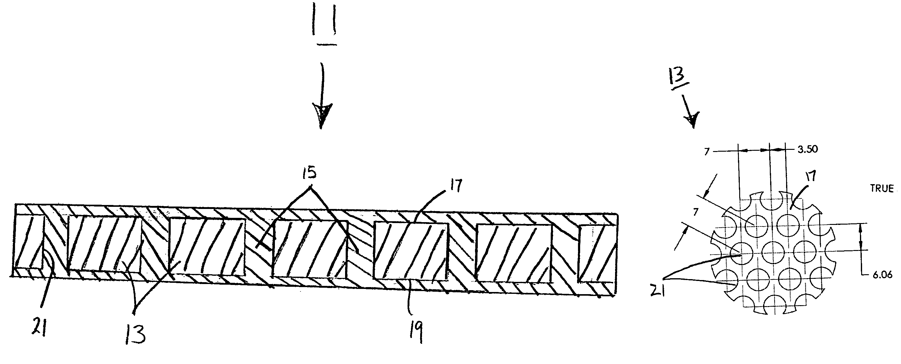
[0029]Referring now to FIG. 1, there is shown a schematic section view of a first embodiment of a solid polymer electrolyte composite membrane constructed according to the teachings of the present invention, said solid polymer electrolyte composite membrane being represented generally by reference numeral 11.

[0030]Composite membrane 11 comprises a non-electrically-conductive support 13 and a solid polymer electrolyte 15, support 13 being impregnated with solid polymer electrolyte 15.

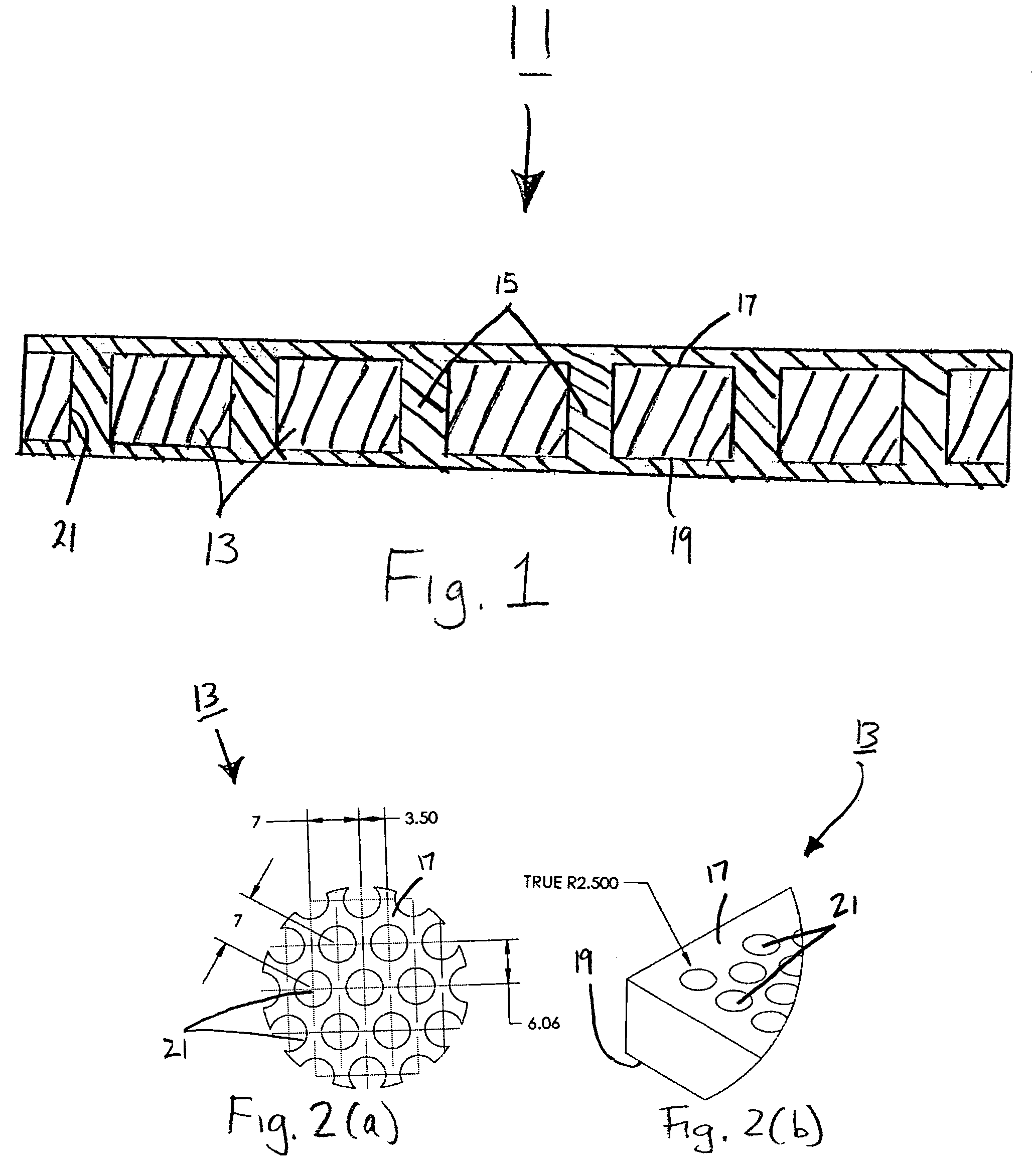
[0031]Referring now to FIGS. 2(a) and 2(b), support 13 can be seen to be a generally sheet-like, unitary structure, preferably of high mechanical strength, having a top surface 17 and a bottom surface 19. The thickness of support 13 may vary, depending upon the type of use to which membrane 11 is put and the types of pressures typically encountered by support 13 in such a use. For example, where membrane 11 is used in an electrolyzer, support 13 preferably has a thickness suitable for withstanding pressu...


PUM

PropertyMeasurementUnit
diameteraaaaaaaaaa
diameteraaaaaaaaaa
thicknessaaaaaaaaaa

Abstract

A solid polymer electrolyte composite membrane and method of manufacturing the same. According to one embodiment, the composite membrane comprises a rigid, non-electrically-conducting support, the support preferably being a sheet of polyimide having a thickness of about 7.5 to 15 microns. The support has a plurality of cylindrical pores extending perpendicularly between opposing top and bottom surfaces of the support. The pores, which preferably have a diameter of about 0.1 to 5 microns, are made by plasma etching and preferably are arranged in a defined pattern, for example, with fewer pores located in areas of high membrane stress and more pores located in areas of low membrane stress. The pores are filled with a first solid polymer electrolyte, such as a perfluorosulfonic acid (PFSA) polymer. A second solid polymer electrolyte, which may be the same as or different than the first solid polymer electrolyte, may be deposited over the top and / or bottom of the first solid polymer electrolyte.

Description

CROSS-REFERENCE TO RELATED APPLICATIONS[0001]The present application claims the benefit under 35 U.S.C. 119(e) of U.S. Provisional Patent Application Ser. No. 60 / 613,769, filed Sep. 28, 2004, the disclosure of which is incorporated herein by reference.STATEMENT REGARDING FEDERALLY SPONSORED RESEARCH OR DEVELOPMENT[0002]The U.S. Government has a paid-up license in this invention and the right in limited circumstances to require the patent owner to license others on reasonable terms as provided for by the terms of Contract No. DE-FG36-04GO13029 awarded by the Department of Energy.BACKGROUND OF THE INVENTION[0003]The present invention relates generally to solid polymer electrolyte membranes of the type suitable for use in electrochemical devices and relates more particularly to a novel such membrane.[0004]Electrochemical devices of the type comprising a solid polymer electrolyte membrane (PEM) sandwiched between a pair of electrodes are well-known, such electrochemical devices finding ...

Claims


Application Information

Patent Timeline
Patent Type & Authority Patents(United States)
IPC IPC(8): H01M2/14C25B13/00
CPCC25B13/02H01G9/0036H01G9/025H01G9/038H01G11/56H01M8/1018H01M8/1023H01M8/1039H01M8/1053H01M8/106H01M8/1062H01M2300/0091Y02E60/13Y02E60/521Y02P70/50Y02E60/50H01G11/84
Inventor LIU, HANLACONTI, ANTHONY B.
Owner PLUG POWER
Why Eureka
Try Eureka