Charged particle beam apparatus and methods for capturing images using the same

a charge particle and beam technology, applied in the field of charge particle beam apparatus, can solve the problems of reduced measurement reproducibility and instrumental error, and achieve the effect of eliminating instrumental error and reducing the variation of cd valu

Active Publication Date: 2010-10-05
HITACHI HIGH-TECH CORP
View PDF8 Cites 11 Cited by
  • Summary
  • Abstract
  • Description
  • Claims
  • Application Information

AI Technical Summary

Benefits of technology

[0009]The present invention provides an electron microscope apparatus with high measurement reproducibility by decreasing the variation in the CD value caused by the variation in the electron beam landing angle. The present invention also provides such a calibration method for decreasing the difference in the electron beam landing angle between apparatuses.
[0014]Since the beam landing angle is equalized regardless of the amount of image shift by performing measurement (b) after performing above-mentioned calibration (a), it becomes possible to eliminate the variation in the CD value caused by the variation in the beam landing angle. Further, since the beam landing angle of each apparatus is substantially equalized by performing the above-mentioned calibration (a) and the measurement (b) with each apparatus, it becomes possible to eliminate the instrumental error caused by the difference in the electron beam landing angle between apparatuses.

Problems solved by technology

This results in reduced measurement reproducibility.
However, although the difference between averages obtained from a large number of measurements is recognized as the instrumental error, it is clear that the instrumental error arises if φa is not equal to φb.

Method used


Image

  • Charged particle beam apparatus and methods for capturing images using the same
  • Charged particle beam apparatus and methods for capturing images using the same
  • Charged particle beam apparatus and methods for capturing images using the same

Examples


modification 1

[Modification 1]

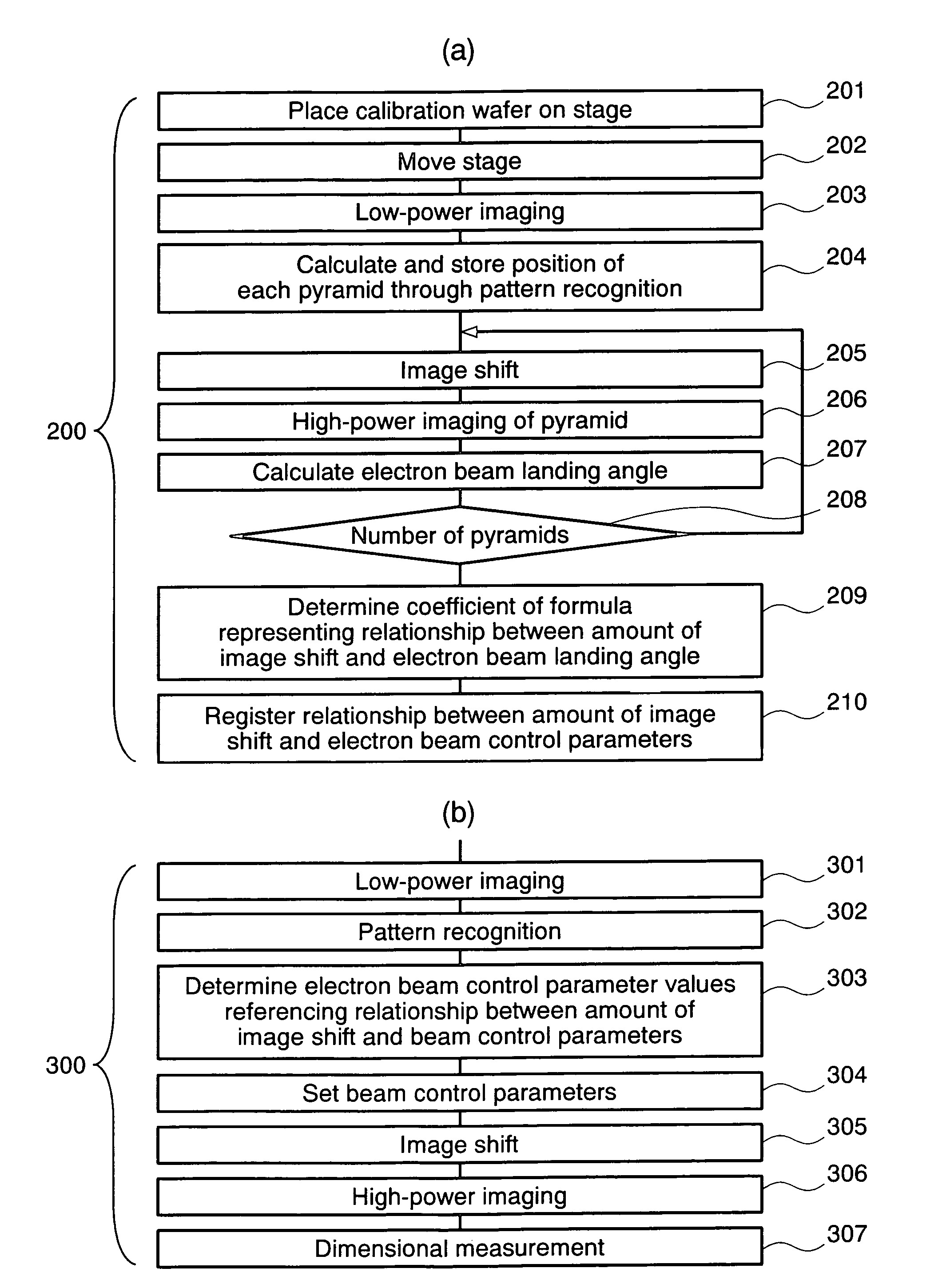
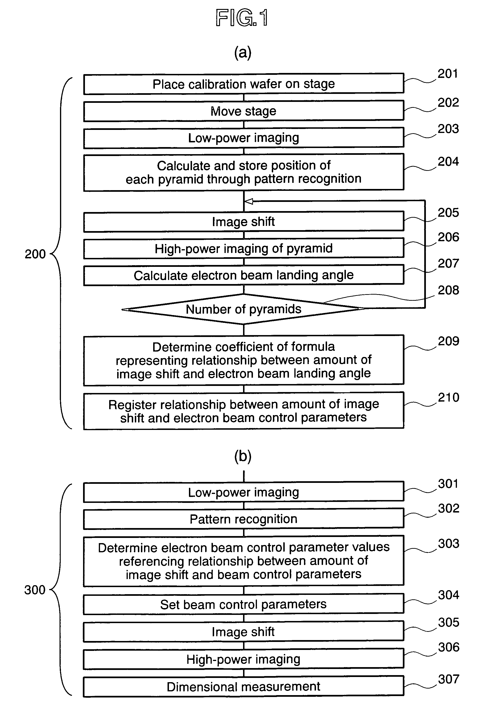
[0055]FIGS. 11A and 11B show a calibration flow chart 200′ and a measurement flow chart 300′ concerning a first Modification, respectively. In the flow charts in FIGS. 11A and 11B, the steps with the same numbers as those in FIG. 1 perform the same processing. In the above-mentioned embodiment, parameters P, Q, dx, and dy in FIG. 5 are obtained in Step 209 in the calibration flow 200. This Modification 1, however, creates a table describing the beam landing angle calculated at the position (x,y) of each pyramid on the viewing field (Step 209′). Then, the present embodiment creates a table describing required beam control parameters (beam incidence conditions for the objective lens, and setup conditions for the focusing lens for correcting the aberration) at each position and then registers these conditions (Step 210′).

[0056]In order to reduce measurement error of the beam landing angle at each position, the obtain beam landing angle φx (i,j) and φy (i,j) at a noticed...

modification 2

[Modification 2]

[0060]FIGS. 12A and 12B show a calibration flow chart 400 and a measurement flow chart 500 concerning Modification 2, respectively. Although the above-mentioned embodiment and Modification 1 intend to make the beam landing angle perpendicular regardless of the amount of image shift, the present embodiment intends to capture inclined images by a predetermined beam landing angle regardless of the amount of image shift. In flow charts in FIGS. 12A and 12B, the steps with the same numbers as those in FIG. 1 perform the same processing.

[0061]In the calibration flow chart 400, Step 401 for setting the beam tilt angle is added prior to Step 203 for capturing low-power images. Also, in the measurement flow chart 500, Step 501 for setting the beam tilt angle is added prior to Step 301 for capturing low-power images. In accordance with the present embodiment, since the beam landing angle becomes a desired tilt angle regardless of the amount of image shift, it is possible to el...

modification 3

[Modification 3]

[0062]The following describes a variation in the polyhedral structure on a sample for beam landing angle calibration.

[0063]In the above-mentioned embodiment, a pyramidal shape produced by the crystal anisotropic etching technology is used as a polyhedral structure on the sample for calibration. A shape which makes it possible to calculate both the electron beam landing angle in the x direction, φx, and the electron beam landing angle in the y direction, φy, by observing a single structure is not limited to a pyramidal shape. For example, as shown in FIG. 15(a), a pyramid with a flat top may be used, which is produced by stopping anisotropic etching halfway. It is possible to obtain a variation in the beam landing angle like a pyramidal shape, for example, by extending line segments 1601 to 1604 in FIG. 15B and obtaining, from the intersection, a virtual apex Q′0 corresponding to the apex Q0 in FIG. 7(b).

[0064]Although FIG. 15A shows an example pyramidal shape with a ...


PUM


Abstract

The present invention provides a charged particle beam apparatus used to measure micro-dimensions (CD value) of a semiconductor apparatus or the like which captures images for measurement. For the present invention, a sample for calibration, on which a plurality of polyhedral structural objects with known angles on surfaces produced by the crystal anisotropic etching technology are arranged in a viewing field, is used. A beam landing angle at each position within a viewing field is calculated based on geometric deformation on an image of each polyhedral structural object. Beam control parameters for equalizing the beam landing angle at each position within the viewing field are pre-registered. The registered beam control parameters are applied according to the position of the pattern to be measured within the viewing field when performing dimensional measurement. Accordingly, the present invention provides methods for reducing the variation in the CD value caused by the variation in the electron beam landing angle with respect to the sample with an equal beam landing angle and methods for reducing the instrumental error caused by the difference in the electron beam landing angle between apparatuses.

Description

BACKGROUND OF THE INVENTION[0001]The present invention relates to a charged particle beam apparatus which measures micro-dimensions, such as circuit patterns of a semiconductor apparatus. More particularly, the present invention is concerned with a method for capturing images through measuring and adjusting an electron beam landing angle with respect to a sample and also concerned with the charged particle beam apparatus.[0002]A CD-SEM (critical dimension scanning electron microscope) designed specifically for semiconductor is used for pattern dimension management in a semiconductor manufacturing process. The principle of the CD-SEM is shown in FIG. 2. A primary electron beam emitted from an electron gun is thinly converged by a convergence lens, and the thus converged electron beam two-dimensionally scans a sample with a scanning coil. An electron beam image can be obtained by capturing secondary electrons generated from the sample by electron beam irradiation, by use of a detector...

Claims


Application Information

Patent Timeline
Patent Type & Authority Patents(United States)
IPC IPC(8): G21K7/00A61N5/00G21G5/00
CPCH01J37/263H01J37/265H01J37/28H01J2237/2826
Inventor SHISHIDO, CHIEOOSAKI, MAYUKASATO, MITSUGUKAWADA, HIROKIMAEDA, TATSUYA
Owner HITACHI HIGH-TECH CORP
Why Eureka
Try Eureka