Inductive magnetic position sensor

a position sensor and magnetic field technology, applied in the field of magnetic field, can solve the problems of inability to meet the needs of many lower-cost applications, large electrical current consumption of magnetostrictive sensors, and expensive devices, etc., and achieve the effects of small size, large measurement area, and low cos

Inactive Publication Date: 2010-10-12
SICK AG
View PDF10 Cites 2 Cited by
  • Summary
  • Abstract
  • Description
  • Claims
  • Application Information

AI Technical Summary

Benefits of technology

[0007]It is an object of the present invention to provide a motion sensor that generates an output signal which is linearly dependent on the position of a magnet which can be inexpensively produced. The sensor should be small in size, mechanically robust and provide a large measurement area while using electronics which are simple and contain only few component parts.
[0014]The motion sensor of the present invention therefore has the advantage that an alternating current signal with a position-dependent amplitude is available as a direct output of the sensor. This makes it simple to process the AC signal into a position-dependent DC voltage or DC current signal as is often desired for industrial applications of the sensor. In addition, the signal generated by the sensor of the present invention has a large signal magnitude and only a small offset signal. This is advantageous because further electronic compensations can be realized without additional cost or can be dropped altogether. It is of course particularly useful and advantageous that the magnetic motion sensor of the present invention generates an output signal with a linear characteristic.
[0015]In a further development of the invention, the sensor can be constructed so that the sum of the windings of all winding layers is approximately equal for each segment width, which increases the linearity of the output.

Problems solved by technology

They require extensive electronics to process the output, which renders the devices costly and not suitable for many lower cost applications.
Such sensors further have mechanically complex sensing elements which are subject to mechanical stresses caused, for example, by vibrations and / or shock loads.
Magnetostrictive sensors additionally consume relatively large amounts of electric current which makes it unfeasible to power such systems with batteries.
Magnetostrictive sensors have an additional disadvantage, particularly when used to measure short measuring distances, because only a relatively small portion of the sensor can actually be used as an electric measurement length.
These sensors have the disadvantage that a multitude of windings must be separately connected and operated, which can only be obtained at relatively high costs.
A disadvantage of this sensor is that, for many applications, the position signals must have linear characteristics.
This significantly limits the largest possible measurement length.
Such a construction increases the available measurement length, but has the disadvantage of an undesirable offset caused by the fact that the maximum inductivity reduction attained by saturation is small relative to the overall inductivity.
Such an offset is undesirable and very costly to electrically compensate.
A further disadvantage of the sensor is that the measurement size, which is position-dependent, is the characteristic of the coil.
As a result, the measured value must first be electronically converted into a direct current or direct voltage signal, which is costly.

Method used


Image

  • Inductive magnetic position sensor
  • Inductive magnetic position sensor

Examples


Embodiment Construction

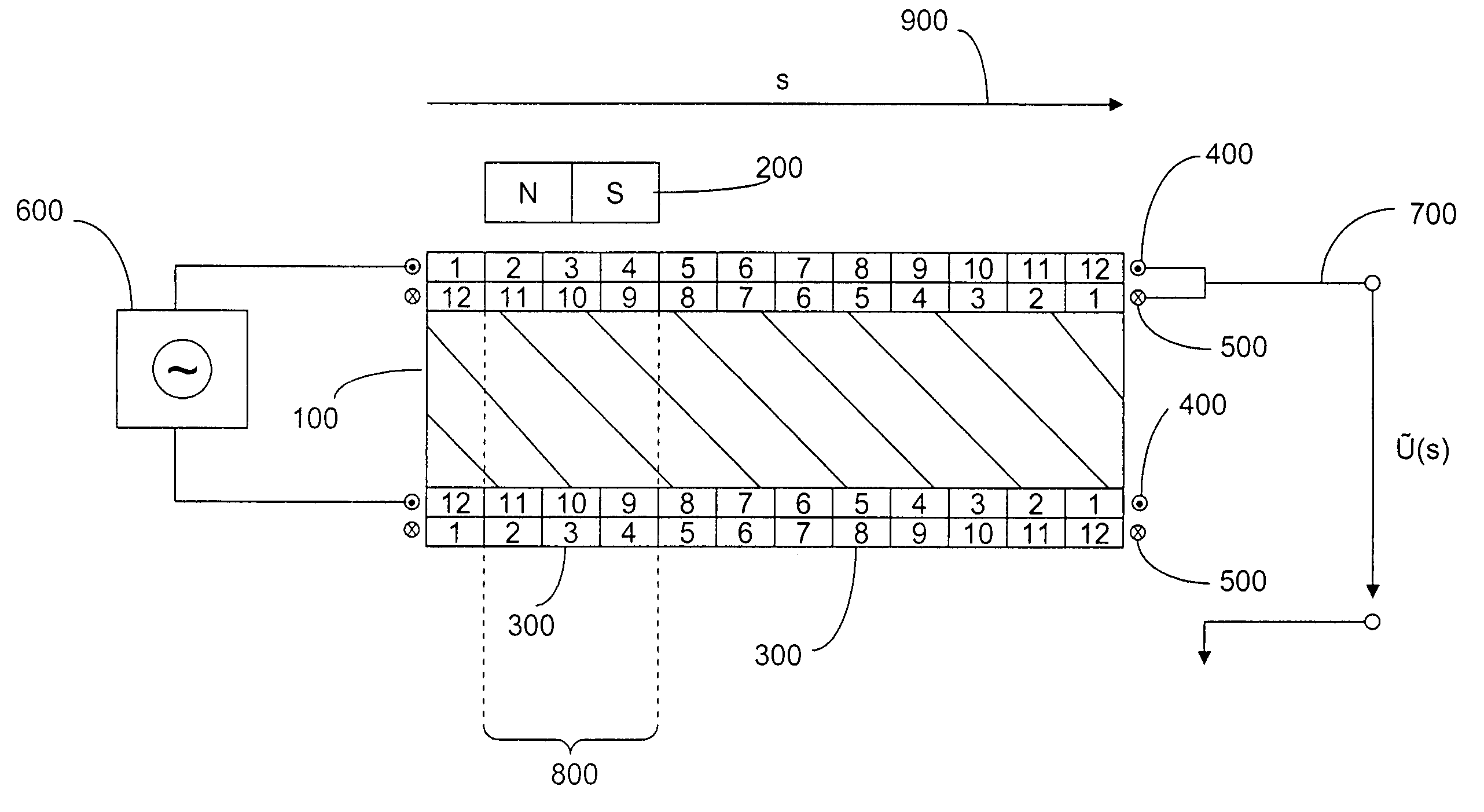
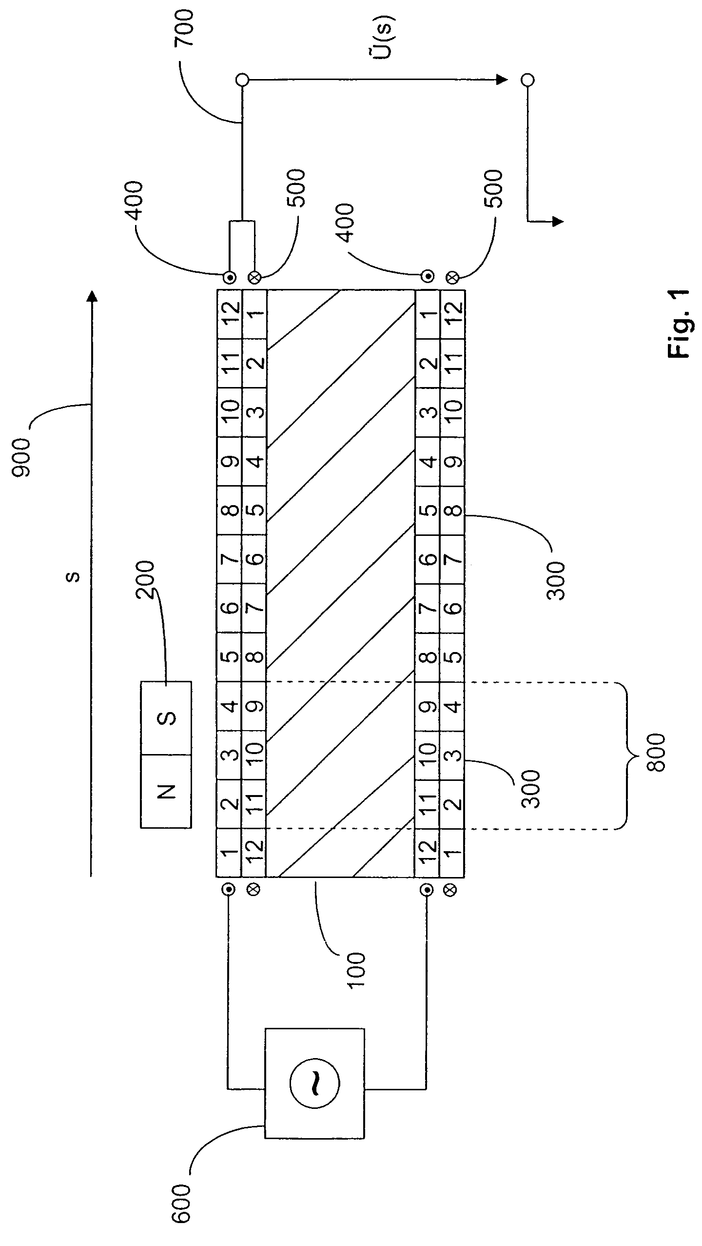
[0018]First and second winding layers 400, 500 surround a ferromagnetic core 100. The winding layers are divided into segments 300 of equal widths. The winding density within any given segment 300 is constant, and the winding density changes linearly from segment to segment over the path length 900. In the inner winding width 500, the respective winding densities decrease over the path length 900 as shown in the drawing by segments 12:11:10 . . . :1.

[0019]In the outer winding layer 400, the respective winding densities increase over the path length 900 as shown in the drawing by segments 1:2:3:4 . . . :12.

[0020]The length of segment 300 preferably is approximately one-third of the longitudinal dimension of magnet 200 that serves as a position indicator.

[0021]The outer winding 400 is wound about ferromagnetic core 100 in the opposite direction to the windings of inner winding layer 500.

[0022]At one end of the sensor, the two windings 400, 500 are electrically connected in series. Bot...


PUM

PropertyMeasurementUnit
lengthaaaaaaaaaa
lengthaaaaaaaaaa
winding densitiesaaaaaaaaaa

Abstract

A motion sensor which has a coil that surrounds a ferromagnetic core and at least one magnet that is longitudinally movable along the coil. The magnet causes a magnetic saturation of the ferromagnetic core in an associated zone that covers a portion of the length of the coil. An evaluation unit generates a position signal in dependence on the position of the movable magnet along the longitudinal extent of the coil. The coil has at least two superimposed winding layers that surround the ferromagnetic core and are wound in opposite directions. The windings of adjacent segments generally have about the same width over which the winding density remains constant. Thus, the winding density of the segments of one of the winding layers increases linearly over the length of the sensor while the winding density of the segments in the other winding layer linearly decreases over the sensor length.

Description

CROSS-REFERENCES TO RELATED APPLICATIONS[0001]This application claims the priority of German Application No. 10 2006 061 771.1, filed Dec. 28, 2006, the disclosure of which is incorporated herein by reference.BACKGROUND OF THE INVENTION[0002]The present invention concerns magnetic motion sensors which generate output signals that have linear characteristics and which include a coil that surrounds a ferromagnetic core and at least one permanent magnet that can be moved in the longitudinal direction of the coil and which causes a magnetic saturation along a zone that is parallel to the ferromagnetic core.[0003]Motion sensors are used, for example, for monitoring the piston travel in hydraulic or automatic systems. Sensors which function according to the magnetostrictive principle are known, but they have their disadvantages. They require extensive electronics to process the output, which renders the devices costly and not suitable for many lower cost applications. Such sensors further...

Claims


Application Information

Patent Timeline
Patent Type & Authority Patents(United States)
IPC IPC(8): G01B7/14H01F5/00
CPCG01D5/2033
Inventor HUBRICH, STEFAN
Owner SICK AG
Why Eureka
Try Eureka