Electron capture detector and nonradiative electron capture detector

a detector and electron capture technology, applied in the field of electron capture detectors, can solve problems such as unfavorable data processing and cumbersomeness, and achieve the effect of high sensitivity and increased free electrons

Inactive Publication Date: 2010-10-12
HITACHI HIGH TECH SCI SYST
View PDF12 Cites 9 Cited by
  • Summary
  • Abstract
  • Description
  • Claims
  • Application Information

AI Technical Summary

Benefits of technology

[0029]According to the present invention, the electron capture detector that uses the discharge in He, that can suppress generation of inverted peaks generated when current between the detection electrodes temporarily rises by ionized organic matters, that has a simple configuration, and that can ensure high sensitivity, the electron capture detection method, and the chromatogram creating apparatus having the electron capture detector can be realized.
[0039]By causing the component lower in ionization potential than the dopant gas to coexist with the dopant gas as the Penning gas, the problem of the emergence of inverted peaks that are regarded as a defect of the nonradiative electron capture detector can be solved. It is, therefore, possible to improve reliability of the nonradiative electron capture detector as a detector and use the detector in various fields.
[0040]By selecting the type of the Penning gas coexisting with the dopant gas, a specific component can be selectively detected. For example, if 3% xenon-containing helium is used as the dopant gas, acetone of the order of several hundreds of ppm is caused to coexist with the dopant gas as the Penning gas (an organic gas component lower in ionization potential than a dopant gas component). It is thereby possible to selectively detect siloxane with high sensitivity. Furthermore, the nonradiative electron capture detector can be used as a high-density selective detector for non-electron-affinic compounds, which is necessary for various fields.

Problems solved by technology

However, because of manual processing, the method is cumbersome and unfavorable for the data processing.

Method used


Image

  • Electron capture detector and nonradiative electron capture detector
  • Electron capture detector and nonradiative electron capture detector
  • Electron capture detector and nonradiative electron capture detector

Examples


Embodiment Construction

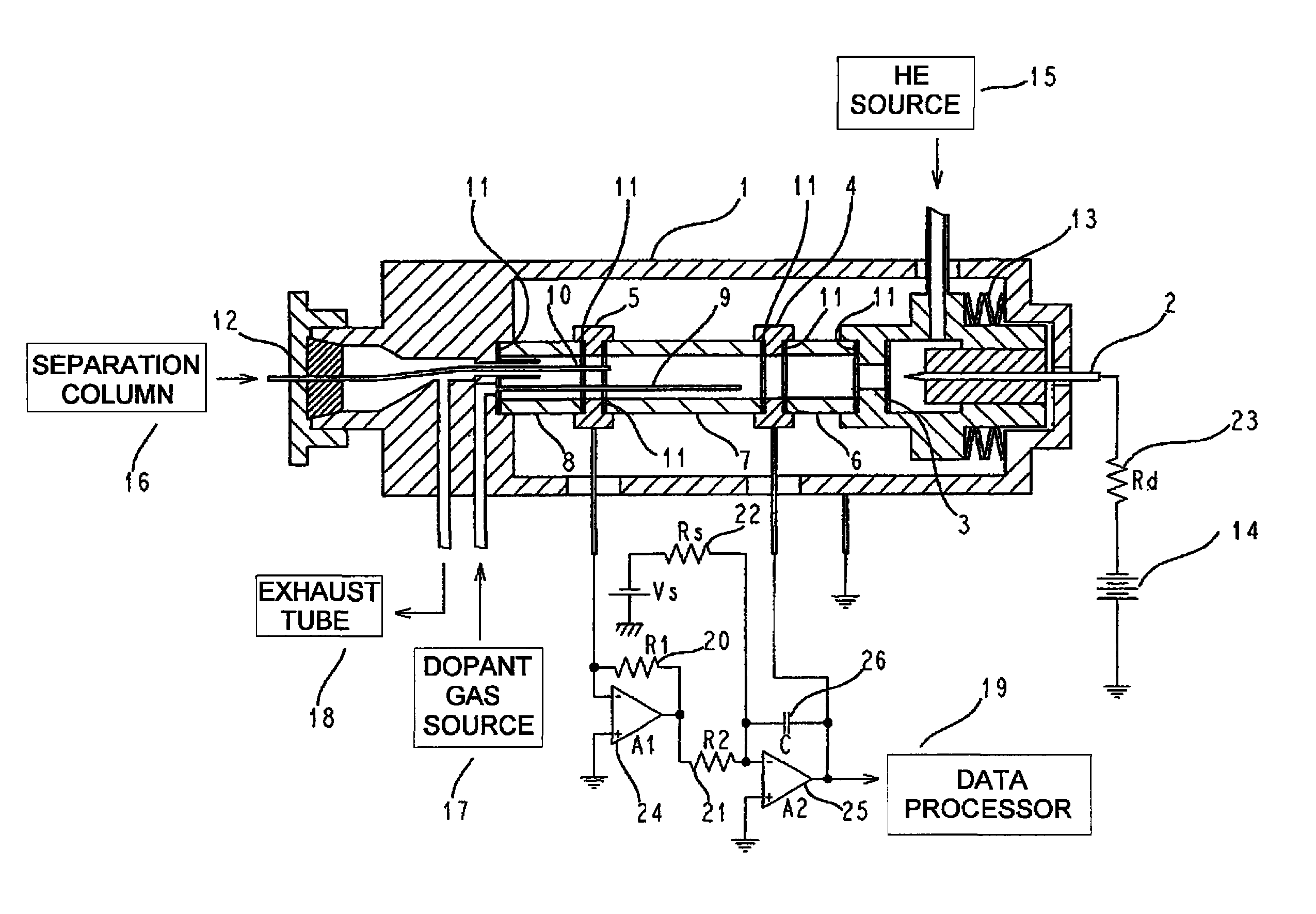
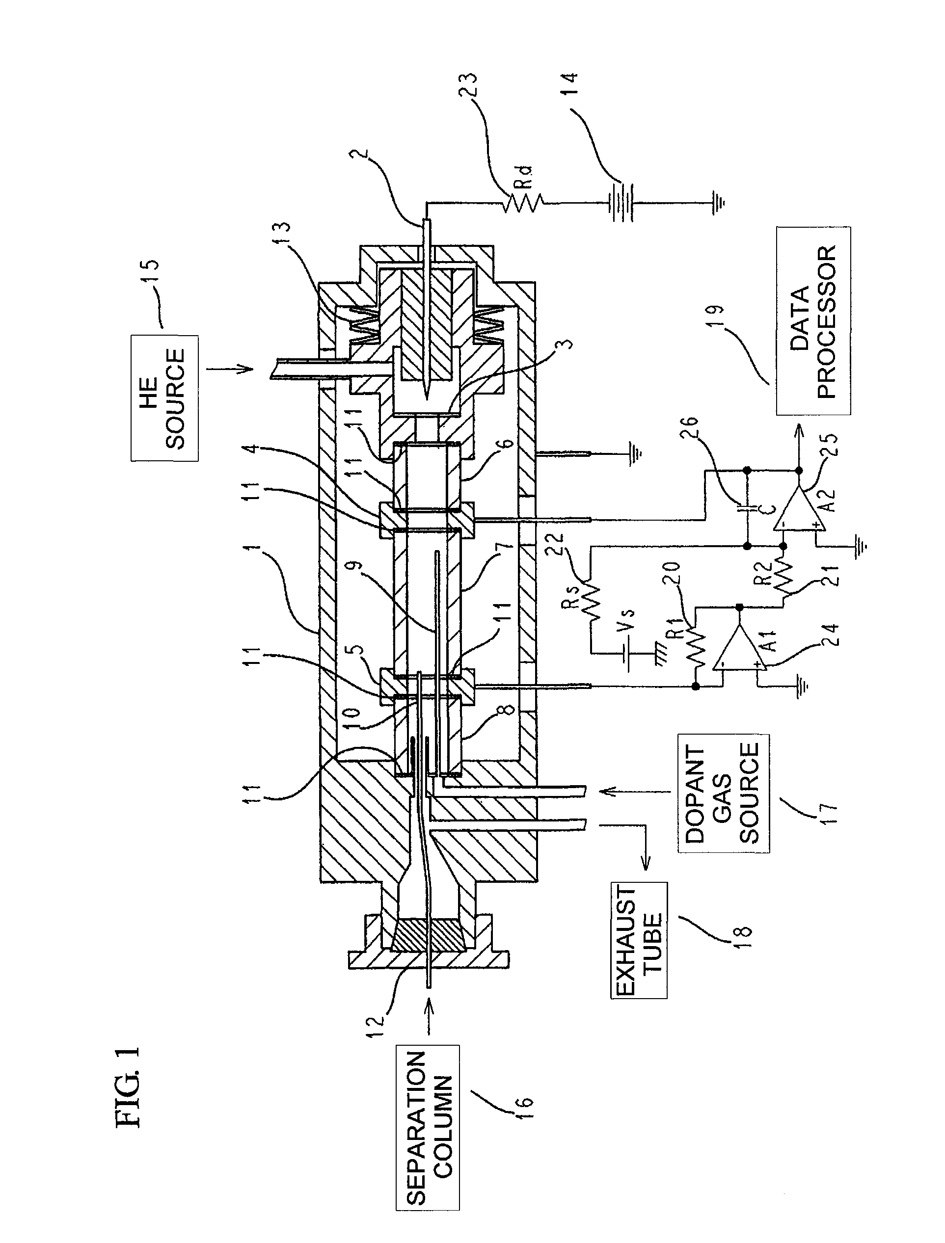
[0056]FIG. 1 is a schematic block diagram of an electron capture detector to which an embodiment of the present invention is applied and a schematic block diagram of a chromatogram creating apparatus having the electron capture detector. In the embodiment shown in FIG. 1, electron capture process is controlled using a direct-current (DC) continuous discharge system, and the electron capture detector having high sensitivity and wide dynamic range is constructed.

[0057]Referring to FIG. 1, a needle-like electrode 2 and a ring-shaped electrode 3 are disposed in a basically axisymmetric discharge chamber to be isolated from each other by 1 mm to 2 mm and opposed to each other. Each of the electrodes 2 and 3 is preferably made of Pt. Further, an appropriate discharge resistance and an appropriate discharge voltage are selected so that a discharge current is 0.1 mA to 2 mA.

[0058]Under the above-stated conditions, it suffices that the discharge voltage is several hundreds of volts, and if a...


PUM

PropertyMeasurementUnit
ionization potentialaaaaaaaaaa
ionization energyaaaaaaaaaa

Abstract

It is intended to realize measuring of trace organic components and to render qualitative procedure efficient through imparting of selectivity. Penning gas and dopant gas are ionized in a space isolated from discharge part with the use of metastable helium obtained by direct-current glow discharge, and with the use of thus obtained plasma, the efficiency of ionization of components to be measured is enhanced, so that intensified ion current can be obtained. Further, through selection of dopant gas and Penning gas, selectivity can be imparted. Thus, not only can measuring of trace organic components be performed but also selectivity can be imparted.

Description

TECHNICAL FIELD[0001]The present invention relates to an electron capture detector for a gas chromatograph, and particularly relates to an electron capture detector generating deep-ultraviolet (deep-UV) rays by generating a discharge in He, ionizing dopant gas by the deep-UV rays, mainly generating negative ions of halogen compound gas using a relatively high electron-density part, and obtaining a signal corresponding to a concentration of a detection target gas using a recombination reaction with ionized positive ions.[0002]The present invention relates to a nonradiative electron capture detector ionizing dopant gas by action of excited helium generated by a glow discharge in helium, measuring a quantity of generated free electrons as a ground current of the detector, and being based on a detection principle of regarding a decrease of the quantity of free electrons based on an electron capture reaction provoked when an electron-affinic detection target component flows into the dete...

Claims


Application Information

Patent Timeline
Patent Type & Authority Patents(United States)
IPC IPC(8): G01N27/62
CPCG01N27/64G01N30/70
Inventor KURITA, SHINJIKAWAMURA, NORIOTAKEUCHI, MASAHIRO
Owner HITACHI HIGH TECH SCI SYST
Why Eureka
Try Eureka