Lowpass-bandstop common mode filter for differential lines carrying high rate digital signals

a lowpass bandstop and digital signal technology, applied in the field of differential data transmission, can solve the problems of em emissions being particularly harmful, affecting the operation of other electronic devices, and radiating unwanted emissions,

Active Publication Date: 2010-10-12
MICROSEMI SOLUTIONS (US) INC
View PDF4 Cites 17 Cited by
  • Summary
  • Abstract
  • Description
  • Claims
  • Application Information

AI Technical Summary

Benefits of technology

[0019]It is an object of the present invention to obviate or mitigate at least one disadvantage of previous common mode filters.

Problems solved by technology

Some devices, like computers and displays, radiate unwanted emissions that can compromise the operation of other electronic devices.
These EM emissions can be particularly harmful if they cause malfunctions of devices, such as pacemakers, and airplane navigation or instrument landing equipment.
Electro-magnetic interference (EMI) requirements are often overlooked by product engineering at the specification phase, and are often an afterthought when the equipment does not meet the specification.
This can lead to very expensive last moment shielding or re-design, which is clearly undesirable.
Likewise, many designs rely on over-designed and heavy shielding, which is not a viable option in many devices, such as open-box equipment.
But the price for such data transmission devices, and fiber itself, is still quite high.
Also, a large number of signals cannot usually be sent differentially and sending signals single-ended usually causes more radiation or more signal distortion.
These discrete frequencies are especially harmful and they are the usual reason a device does not meeting the EMI requirements.
A problem with this kind of EMI reduction is that modulation has to be relatively wide, and, although the receive clock recovery phase lock loop (PLL) can handle it, there can be a problem with first-in-first-out (FIFO) under / over-flow.
However, they cannot achieve more than 10 to 15 dB of attenuation in the frequency range of interest without seriously affecting the differential mode.
For this type of common mode choke, the coupling factor is in the range of 0.7 to 0.9, which leads to substantial attenuation of differential mode signals.
It is also challenging to achieve magnetic coupling factors of even 0.8.
The ferrite based chokes need to be mounted on the top of the PCB and this requires PCB vias that can be detrimental to performance at high frequencies.
Also, the mounting pads for the common mode chokes will present discontinuity.
Having magnetic coupling of approximately 0.8 can also limit the value of the self inductances of high speed data common mode chokes, otherwise the attenuation of the differential mode will be too high.
Therefore, as the values of self-inductances of common mode chokes generally need to be small, the common mode attenuation, which is proportional to the self-inductance, is also not large enough.

Method used


Image

  • Lowpass-bandstop common mode filter for differential lines carrying high rate digital signals
  • Lowpass-bandstop common mode filter for differential lines carrying high rate digital signals
  • Lowpass-bandstop common mode filter for differential lines carrying high rate digital signals

Examples


Embodiment Construction

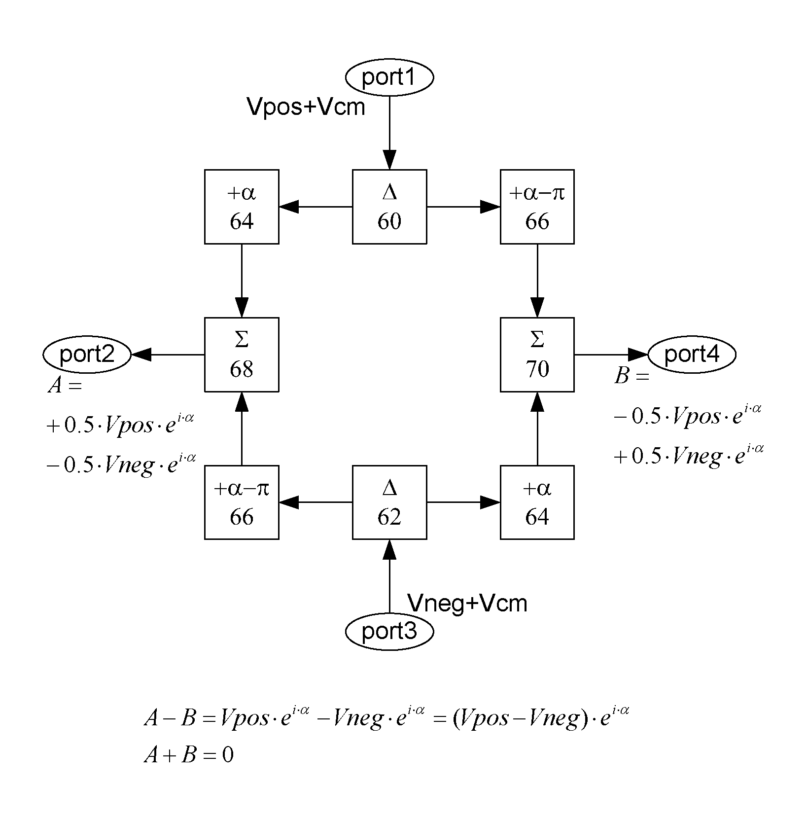
[0050]The present invention provides a structure that can be used to make a common mode filter. Only the common mode is significantly attenuated and the differential mode is not attenuated. This structure can be implemented in a number of ways, a specific embodiment using strip-line, or microstrip line, and slot-line junctions is very compact and well suited to be used with multilayer PCB and does not require any extra components. It can be designed to attenuate certain discrete frequencies, by designing the poles of the transfer function to be at these frequencies. This is an improvement over the common mode choke filters as the spectrum of common mode noise has the highest level spurs at discrete frequencies that are harmonically related to the symbol rate. Embodiments of the present invention result in good return loss of differential signals. Embodiments of the present invention use a strip-line line and slot-line junctions arranged in such a fashion to suppress the common mode ...


PUM


Abstract

The present invention provides a novel structure that can be used to make a common mode filter. Only the common mode will be attenuated and the differential mode will not be attenuated. This structure can be implemented in a number of ways, a specific embodiment using strip-line and slot-line junctions is very compact and well-suited to use with multilayer PCBs, and does not require any extra components. It can be designed to attenuate certain discrete frequencies, by designing the poles of the transfer function to be at these frequencies.

Description

CROSS-REFERENCE TO RELATED APPLICATIONS[0001]The present application claims the benefit of U.S. Provisional Application No. 60 / 892,030, filed Feb. 28, 2007, the contents of which are incorporated herein by reference in their entirety.FIELD OF THE INVENTION[0002]The present invention relates generally to differential data transmission. More particularly, the present invention relates to common mode filtering of signals transmitted over differential transmission lines.BACKGROUND OF THE INVENTION[0003]Technological advances over the last decades have increased the use of electronic devices in many areas of everyday life. The space around people, almost in any area of the world, is immersed in a variety of emitted electro-magnetic waves. These electro-magnetic (EM) emissions vary in power and frequency. Some devices, such as cell phones, claim the spectrum as part of their intended operation. Some devices, like computers and displays, radiate unwanted emissions that can compromise the o...

Claims


Application Information

Patent Timeline
Patent Type & Authority Patents(United States)
IPC IPC(8): H04B3/20H01P3/08
CPCH01P3/02H01P3/08H04B3/30H04L25/0276
Inventor ACIMOVIC, PREDRAG
Owner MICROSEMI SOLUTIONS (US) INC
Why Eureka
Try Eureka