Supercharge Your Innovation With Domain-Expert AI Agents!

Amplifying optical fiber

a technology of optical fiber and amplifier, which is applied in the direction of cladded optical fiber, semiconductor laser, instruments, etc., can solve the problems of not being able to transfer the energy absorbed by the quantum dots to the dopant efficaciously, reducing the efficacy of optical conversion and therefore the amplification of optical signals to be amplified, and not being able to achieve satisfactory solutions

Active Publication Date: 2010-10-12
WSOU INVESTMENTS LLC
View PDF13 Cites 0 Cited by
  • Summary
  • Abstract
  • Description
  • Claims
  • Application Information

AI Technical Summary

Benefits of technology

This design enhances energy transfer between quantum dots and dopants, reducing ion cooperation and diffusion losses, thereby improving optical signal amplification efficiency and extending the length of the fiber while maintaining high conversion efficiency.

Problems solved by technology

It is not possible with the current technology to insert a sufficient concentration of dopant over this short a distance, so that it is not possible to transfer the energy absorbed by the quantum dots to the dopant efficaciously.
This solution is not yet satisfactory, however.
This causes cooperation between the ions of the dopant, which greatly reduces the efficacy of the optical conversion and therefore the amplification of the optical signal to be amplified.
Moreover, a coupling loss cannot be avoided between a flat waveguide and a circular line fiber.

Method used


Image

  • Amplifying optical fiber
  • Amplifying optical fiber

Examples


first embodiment

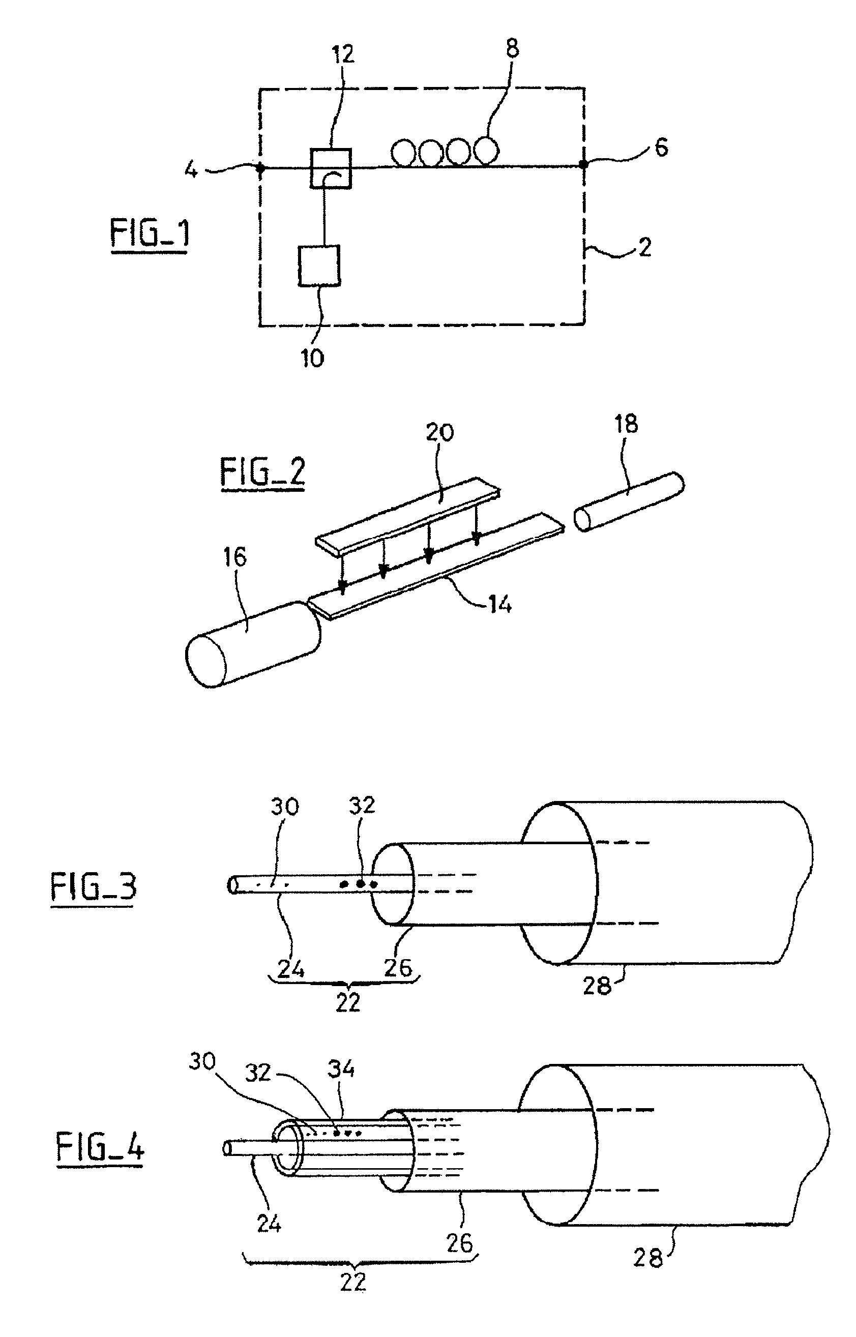
[0023]There is represented in perspective in FIG. 3 an amplifying optical fiber according to the invention. This optical fiber comprises a core 22, which is formed of a monomode core 24 surrounded by a multimode core 26, and a cladding 28.

[0024]The monomode core 24 comprises a dopant 30 for amplifying an optical signal propagating in the monomode core. The dopant may be of any known type, and in particular a rare earth, and in particular erbium. The monomode core also comprises quantum dots 32 of a semiconductor material.

[0025]The multimode core 26 is intended to receive a pumping optical signal. Thus, in contrast to the prior art represented in FIG. 2, the invention enables the pumping signal to propagate over a great distance before being absorbed by the quantum dots 32. The absorption of the pumping signal in the multimode core is inversely proportional to the diameter of the multimode core. The fact of providing a greater length for the absorption of the pumping optical signal e...

second embodiment

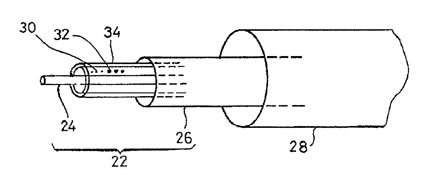
[0029]There is represented in FIG. 4 an amplifying optical fiber according to the invention. Elements identical to those in FIG. 3 carry identical reference numbers.

[0030]The FIG. 4 embodiment differs from that of FIG. 3 in that the particles 30 of dopant and the semiconductor material quantum dots 32 are disposed in a ring 34 around the monomode core 24.

[0031]This embodiment reduces the size of the multimode core. Thus if the position and the size of the ring are such that the integral of the overlap between the monomode signal and the doped area is reduced by a factor of 3.33 relative to the doping in the core, the diffusion losses are reduced by a factor of 3.33. Moreover, the diameter of the multimode core may be reduced by a factor of 10 compared to the previous situation. In this embodiment, the diameter of the multimode core is therefore 40 μm and the length of the fiber is of the order of 70 m.

[0032]This arrangement also reduces the losses caused by diffusion generated by th...


PUM


Abstract

The invention consists in an amplifying optical fiber comprising a core containing a dopant and a cladding, wherein said core comprises a monomode core intended to propagate an optical signal, quantum dots of a semiconductor material being disposed in or near said monomode core, and a multimode core surrounding the monomode core, intended to receive a pumping signal.

Description

CROSS-REFERENCE TO RELATED APPLICATIONS[0001]This application is a divisional application of U.S. application Ser. No. 11 / 556,753 filed Nov. 6, 2006 based on French Patent Application No. FR 0553374 filed Nov. 8, 2005, the priority of which is hereby claimed under 35 U.S.C §119. The disclosures of all of the above applications are hereby incorporated by reference thereto in their entirety.BACKGROUND OF THE INVENTION[0002]1. Field of the Invention[0003]The present invention concerns the field of amplifying optical fibers and of optical fiber amplifiers.[0004]2. Description of the Prior Art[0005]There is represented diagrammatically in FIG. 1 an optical fiber amplifier. This amplifier 2 comprises an input port 4 and an output port 6 intended to be connected to a line fiber. The amplifier consists of a doped optical fiber 8, a pumping source 10 and an optical coupler 12. The pumping source is generally a laser and delivers a pumping optical signal that is injected into the doped fiber ...

Claims


Application Information

Patent Timeline
Patent Type & Authority Patents(United States)
IPC IPC(8): G02B6/00
CPCB82Y20/00H01S3/06716H01S3/06754H01S3/094003G02B6/0229H01S3/094007H01S3/169H01S5/041H01S5/3412
Inventor SIMONNEAU, CHRISTIANGASCA, LAURENTBLANCHANDIN, STEPHANIEBAYART, DOMINIQUE
Owner WSOU INVESTMENTS LLC
Features
  • R&D
  • Intellectual Property
  • Life Sciences
  • Materials
  • Tech Scout
  • Unparalleled Data Quality
  • Higher Quality Content
  • 60% Fewer Hallucinations
Learn More