
Method for determining average properties of molecules in solution

a technology of average properties and molecules, applied in the field of method for determining average properties of molecules in solution, can solve the problems of increasing error in wyatt peak method, increasing error in virial coefficient calculation, and broadening effect introducing errors into calculation, so as to achieve the effect of increasing automation

Active Publication Date: 2010-10-12
WYATT TECH LLC
View PDF5 Cites 2 Cited by
  • Summary
  • Abstract
  • Description
  • Claims
  • Application Information

AI Technical Summary

Benefits of technology

This method enables precise calculation of virial coefficients with minimal sample quantities, reduces errors associated with inter-detector broadening, and automates the dialysis process, improving accuracy and efficiency in determining molecular characteristics and cross-virial interactions.

Problems solved by technology

(1) to the sequential values of the light scattering and concentration leads to some degree of error in calculating the virial coefficients.
The error in the Wyatt peak method increases both as the interdetector broadening increases, and as the deviation of the MALS signal from linear dependence on concentration increases, i.e. with larger FOM.
Again, the broadening effect introduces errors into the calculation.
The limitation of this method is that it does not work well for large broadening, and it requires extra effort to determine the correction factor a priori.
One drawback of the dRI measurement is the necessity for completely dialyzing protein samples against the solvent, for the very reason that the dRI detector is sensitive to the salts and excipients, as well as dissolved gasses, that may be present in the protein sample but not in the pure buffer.
However, dialysis can be a tedious and time-consuming process, and a means of combining the flowing peak measurement with in-line dialysis would be advantageous in automating these measurements.

Method used


Image

  • Method for determining average properties of molecules in solution
  • Method for determining average properties of molecules in solution
  • Method for determining average properties of molecules in solution

Examples


first embodiment

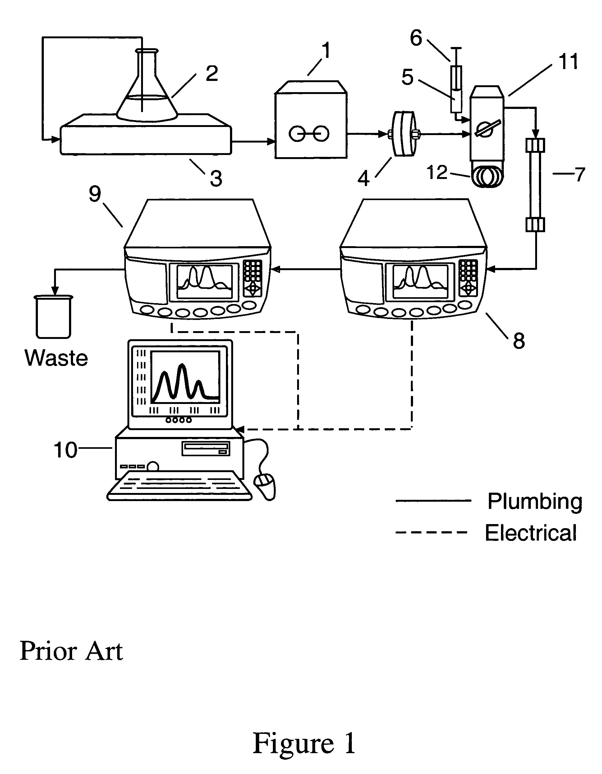
[0048]In a first embodiment denoted the “injection valve method”, depicted in FIG. 1, solvent is drawn by pumping means 1 from a solvent reservoir 2 through a degasser 3 and then pumped through filter means 4 to the injection valve 11 and on to the detectors 8 and 9. The degasser 3 is generally used to remove dissolved gasses from the solvent as such gasses might subsequently produce small bubbles in solution that could interfere with the desired measurements from the solution itself. Filter means 4 is generally incorporated as shown to remove residual particulate material from said solvent that could interfere with the desired measurements. One example of the pumping means is the model G1310 isocratic pump from Agilent Technologies, Inc., Santa Clara, Calif. An example of a degasser is the Systec Multi-Channel Vacuum Degasser, available from Upchurch Scientific, Oak Harbor, Wash. The solvent passes through the injection valve 11 set to bypass position so that the solvent does not f...

second embodiment

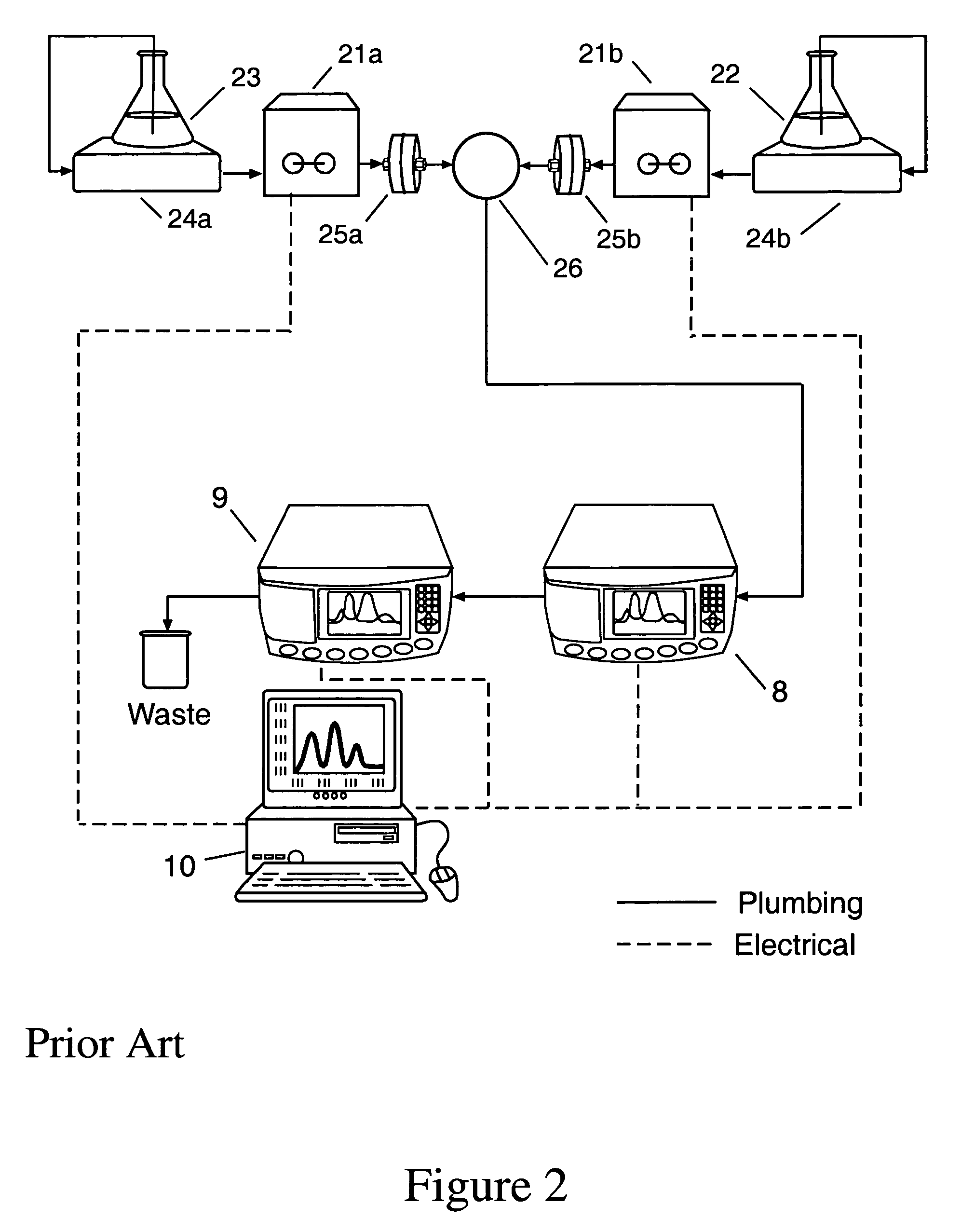
[0049]In a second embodiment denoted the “dual-pump method”, depicted in FIG. 2, two computer-controlled pumps 21a and 21be.g. the Microlab 500 Dual-Syringe Diluter / Dispenser, Hamilton Corp., Reno, Nev., comprises two independently controllable syringe pumps, are used to draw sample from a sample reservoir 22 and solvent from a solvent reservoir 23. These are transferred through degasser chambers 24a and 24b and pumped through filters 25a and 25b. The flow rates of the two pumps are adjusted by means of the computer, and the streams combined and pumped through a mixing chamber, e.g. the Hypershear in-line static mixer, available from Analytical Scientific Instruments, El Sobrante, Calif., in order to produce a continuous stream of sample at the desired concentration. The mixed sample may be temporarily stored in a holding volume 26 which includes the mixing chamber, tubing, desalting column, and any additional volume as may be required. After the desired volume of mixed sample has b...

third embodiment

[0050]As would be evident to those skilled in the art, a third embodiment would create sequential sample concentrations with a pair of pumps as per the dual pump method, injecting the mixed sample into a sample loop, and the sample would be pushed on to the detectors by an additional pumping means upon switching the injection valve, as per the injection valve method.

[0051]In the event that the sample requires prior dialysis, a desalting column 7, e.g., the HiTrap desalting column, available from Amersham BioSciences, Uppsala, Swede, may be placed before the MALS detector 8.

[0052]Each successive sample 5 passes through the MALS detector 8, whereby the values of the excess Rayleigh ratio at each angle, Rj(θk), are measured at successive elution volumes Δvj; and through a concentration detector 9, shown as a differential refractive index (dRI) detector, whereby the sample concentration ci is measured at each volume interval Δvi. The resultant light scattering and concentration signals ...


PUM

PropertyMeasurementUnit
volumesaaaaaaaaaa
volumeaaaaaaaaaa
volumesaaaaaaaaaa

Abstract

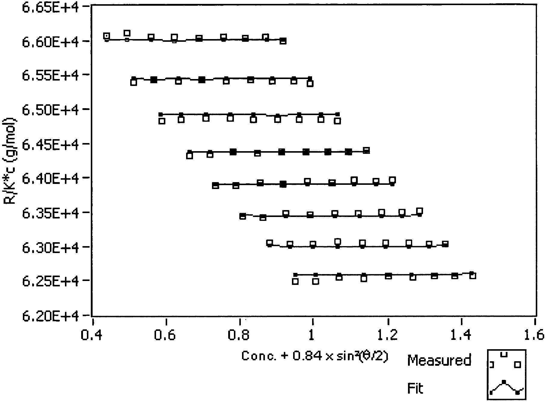
A new method is presented for measuring the molecular properties of an unfractionated solution of macromolecules. Sample aliquots spanning a range of concentrations are injected sequentially into a stream of solution and flow towards the detectors. Each aliquot produces, thereby, an effective “peak” whose elements correspond to different concentrations of the diluted aliquot. The weight averaged molar mass, the mean square radius, and the second virial coefficient of the macromolecules in solution are derived from an analysis of the angular and concentration dependence of the scattering signals throughout the corresponding peaks. In contrast to earlier on-line methods, better accuracy is achieved, while using a smaller quantity of sample. A similar method for determining cross virial coefficients between two distinct species of macromolecules is also presented.

Description

BACKGROUND[0001]Molecules in solution are generally characterized by their weight averaged molar mass M, their mean square radius <rg2>=∫r2dm / ∫dm (here r is the distance from the center of mass of the molecule and dm the mass of a small volume at that distance), and the second virial coefficient A2. In some cases, the third virial coefficient A3 is also of interest. In other cases, the cross-virial coefficient A2AB between two distinct molecules A and B is of interest. M and <rg2> are properties of the individual molecules, averaged over all the molecules in the solution; the virial coefficients are a measure of the average interaction between the molecules as mediated by the solvent. For unfractionated solutions, these properties may be determined by measuring the manner by which they scatter light using the method described by Bruno Zimm in his seminal 1948 paper which appeared in the Journal of Chemical Physics, volume 16pages 1093 through 1099. The light scattered fr...

Claims


Application Information

Patent Timeline
Patent Type & Authority Patents(United States)
IPC IPC(8): G01N31/00
CPCG01N15/0205G01N35/085G01N35/1095G01N2035/1032G01N2021/4711
Inventor SOME, DANIEL I.TRAINOFF, STEVEN P.
Owner WYATT TECH LLC
Learn More