Method of predicting residual service life for rolling bearings and a device for predicting residual service life for rolling bearings

a technology of rolling bearings and service life, which is applied in the direction of liquid fuel engines, machines/engines, instruments, etc., can solve the problems of unexpected problems of rolling bearings, interruption of machinery operation, and inconvenience of rolling bearing maintenance, so as to simplify the management of diagnostic results and ensure the effect of maintenance efficiency

Inactive Publication Date: 2010-10-12
THE CHUGOKU ELECTRIC POWER CO INC +1
View PDF11 Cites 16 Cited by
  • Summary
  • Abstract
  • Description
  • Claims
  • Application Information

AI Technical Summary

Benefits of technology

[0032]The present invention, accordingly, regularizes replacement cycles, enabling more efficient maintenance of mechanical rotating devices (1, 2), because the residual service life of rolling bearings (3) residing on a mechanical rotating device (1, 2) can be predicted while the device is in operation. For instance, a schedule can be easily implemented to replace rolling bearings (3) residing on mechanical rotating devices (1, 2) in power plants in autumn, instead of summer, where operating rates are higher, enabling more efficient maintenance. Further, because of the lack of precision with traditional methods of predicting residual service life, for machinery with rotating elements that require regular inspection, the present invention makes it possible to predict residual service life earlier, meaning the interval between regular inspections can be extended, and data related to the degradation of rolling bearings can be made more readily available; thus, a more efficient system of maintenance can be anticipated when moving from a traditional system of regularly scheduled inspections to a maintenance system based on the specific condition of each machine.
[0034]The device for predicting residual service life as comprised above uses signals from an accelerometer (4) in resonant frequencies or high frequencies to detect, in a cost-effective manner, lubricant penetration by wear particles and lubricant degradation, and in the early stages accurately estimates rolling bearing (3) service life, using as a basis the measured wear particle penetration levels and lubricant degradation levels.
[0036]The present invention, accordingly, regularizes replacement cycles and extends replacement intervals through use of the output device for inspection schedules and diagnostic reports (10), enabling more efficient maintenance of mechanical rotating devices (1, 2), because the residual service life of rolling bearings (3) residing on a mechanical rotating device (1, 2) can be predicted while the device is in operation. For instance, a schedule can be easily implemented to replace rolling bearings (3) residing on mechanical rotating devices (1, 2) in power plants in autumn, instead of summer, where operating rates are higher. Further, for machinery where traditionally regular inspection could not be avoided, the present invention makes it possible to predict residual service life earlier, meaning the interval between regular inspections can be extended, and data related to the degradation of rolling bearings can be made more readily available; thus, a more efficient system of maintenance can be anticipated when moving from a traditional system of regularly scheduled inspections to a maintenance system based on the specific condition of each machine.
[0037]A data transmission modem (11) that connects said waveform data and diagnostic results to the Internet network is further included. Using said data transmission modem (11) enables acquisition of simply vibration data alone from a remote location, and prediction of residual service life for rolling bearings (3) located in a fixed location can be accomplished from remote locations, further simplifying management of diagnostic results.

Problems solved by technology

Rolling bearings in large numbers are found being used in the rotating components of a wide variety of machineries, and when these rolling bearings fail to work properly, various inconveniences can result, such as interruption in operation of the machinery.
Mechanical problems causing stress, such as unsuitable lubricant, misalignment of the rotating shaft, or improper assembly of rolling bearings, can cause unexpected problems for rolling bearings.
The majority of rolling bearing problems are caused by inadequate lubrication, the result of such factors as wear particle penetration and lubricant degradation.
Generally, at the instant the rolling element (or roller) and the bearing ring of a rolling bearing come into direct contact, unique vibrations occur, and large amounts of stress focalize under the surface of the material, creating pressure waves in the material.
However, with the traditional prediction methods described above, setting the activation barrier for vibrations is difficult, and residual service life varies greatly depending on the activation barrier; thus, making accurate predictions of residual service life is extremely difficult.
Further, by the time vibrations begin increasing, the rolling bearing is already in the stage of total fatigue failure, making the creation of long-term maintenance plans difficult; moreover, even when prediction of residual service life is carried out, repairs may not be implemented in time.
As a result, in practice, rolling bearings are often replaced in the early stages, despite the fact that they may not yet be close to the end of their true service life.
Further, because of the poor precision in predicting residual service life for these methods, at actual power plants, factories and similar facilities, it is impossible to extend the interval between inspection cycles, necessitating maintenance systems where every single bearing is replaced during set inspection times every few years.
The inability of these methods to reduce costs and labor—which is the main purpose of maintenance—is thus a problem.
Again, although the said traditional Shock Pulse Method can detect lubricant degradation in the early stages and determine appropriate intervals for lubricant supplementation, it still has the limitation of not being able to make precise predictions regarding residual service life based on the current conditions.
Further, although the traditional AE Method can predict residual service life at an earlier stage than the said statistical methods using vibration acceleration, the AE (Acoustic Emission) sensor and the signal processing circuit that are used for predictions are cost-prohibitive; in addition, AE waves are very faint, making the method prone to noise interference.

Method used


Image

  • Method of predicting residual service life for rolling bearings and a device for predicting residual service life for rolling bearings
  • Method of predicting residual service life for rolling bearings and a device for predicting residual service life for rolling bearings
  • Method of predicting residual service life for rolling bearings and a device for predicting residual service life for rolling bearings

Examples


Embodiment Construction

[0049]The preferred embodiments of the present invention will be described in detail with reference to the accompanying drawings.

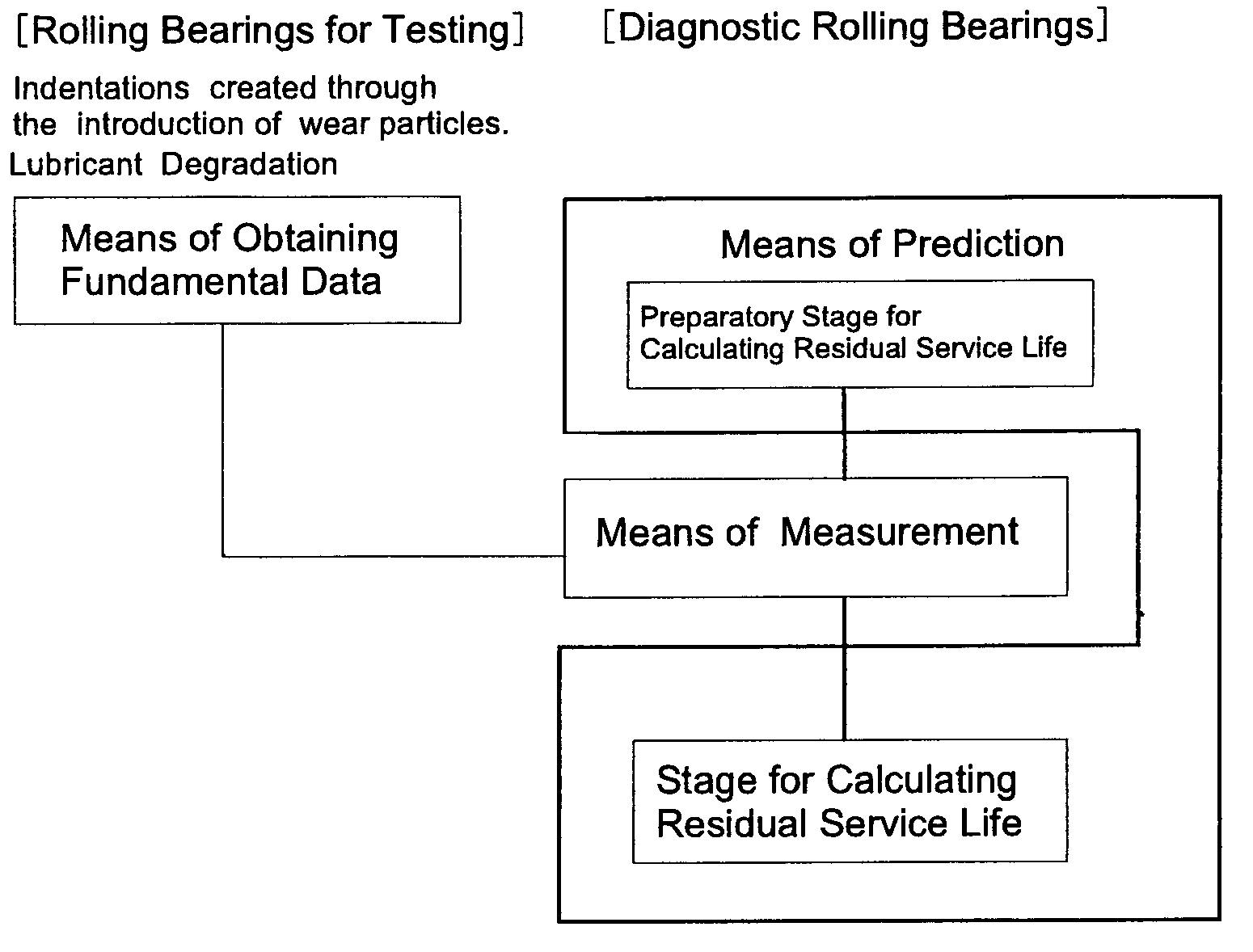
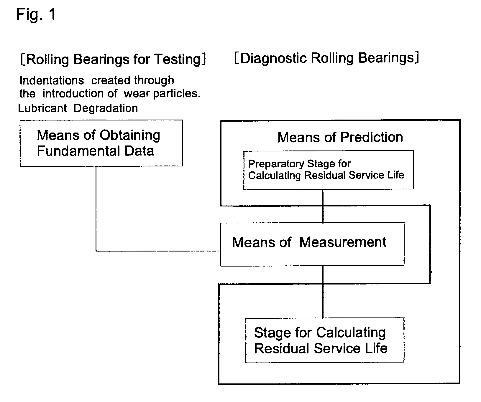
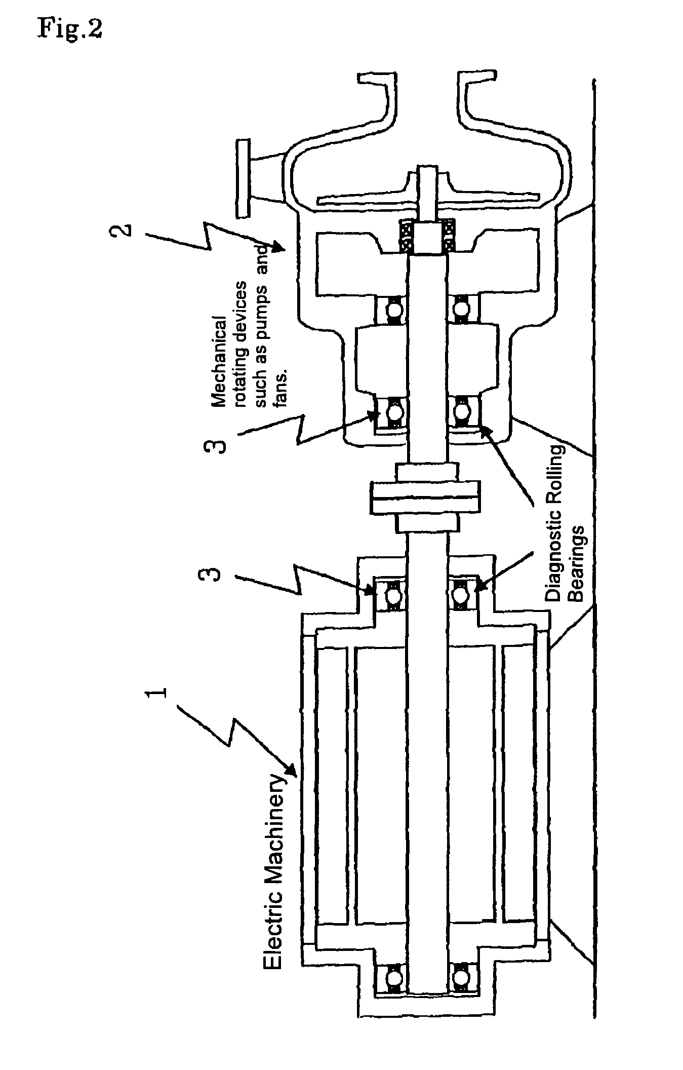
[0050]FIG. 1 is a block diagram illustrating the method of predicting residual service life for rolling bearings for the present invention. FIG. 2 is a cross-sectional example of the rolling bearings that reside on electric machinery or mechanical rotating devices, and that are the object of the predictions for the method of predicting residual service life. FIG. 3 is a flow chart illustrating the method of predicting residual service life for rolling bearings. FIG. 4 is a flow chart illustrating Step A (the preparatory stage for calculating residual service life used for the means of prediction) of the flow chart shown in FIG. 3. FIG. 5 is a flow chart illustrating Step B (the means of measurement) of the flow chart shown in FIG. 3. FIG. 6 is a flow chart illustrating Step C (the residual service life calculation stage used for the means of prediction) of...


PUM


Abstract

A method that utilizes signals from an accelerometer in resonant frequency bands or high frequency bands to, in a cost-effective manner, measure wear particle penetration of lubricant and lubricant degradation, both of which greatly affect prediction of residual service life; and, using as a basis these measurements of wear particle penetration and lubricant degradation, enables accurate estimation of residual service life for rolling bearings in the early stages.

Description

BACKGROUND OF THE INVENTION[0001]1. Field of the Invention[0002]The present invention is related to a method of predicting residual service life for rolling bearings and a device for predicting residual service life for rolling bearings that estimates the remaining service life of rolling bearings residing on mechanical rotating devices such as pumps and fans.[0003]2. Description of the Related Art[0004]Rolling bearings in large numbers are found being used in the rotating components of a wide variety of machineries, and when these rolling bearings fail to work properly, various inconveniences can result, such as interruption in operation of the machinery. Generally, rolling bearings provide superb performance, and have, when used under proper conditions, long service lives, which last until repeated stress causes spalling. However, service life varies not only according to usage conditions and environment; it can even vary within identical machinery and bearings.[0005]Mechanical pr...

Claims


Application Information

Patent Timeline
Patent Type & Authority Patents(United States)
IPC IPC(8): G06G7/48G01H1/00G01M13/04G01H17/00G01M99/00
CPCG01M13/045G01H1/003G01M13/04G01M99/008F04D29/04G01H17/00G01H13/00
Inventor SHIROMARU, ISAOTANAKA, MAKOTOAKAMATSU, YOSHINOBUNAGAYASU, YOJIBODA, SHINGOIWATSUBO, TAKUZO
Owner THE CHUGOKU ELECTRIC POWER CO INC
Why Eureka
Try Eureka