Molecular sensors for explosives

a technology of explosives and sensors, applied in the field of methods for detecting explosives, can solve the problems of inconvenient use in the field of current mass spectrometric systems, and achieve the effect of convenient operation and rapid communication

Inactive Publication Date: 2010-11-02
AVIRAM ARI
View PDF7 Cites 24 Cited by
  • Summary
  • Abstract
  • Description
  • Claims
  • Application Information

AI Technical Summary

Benefits of technology

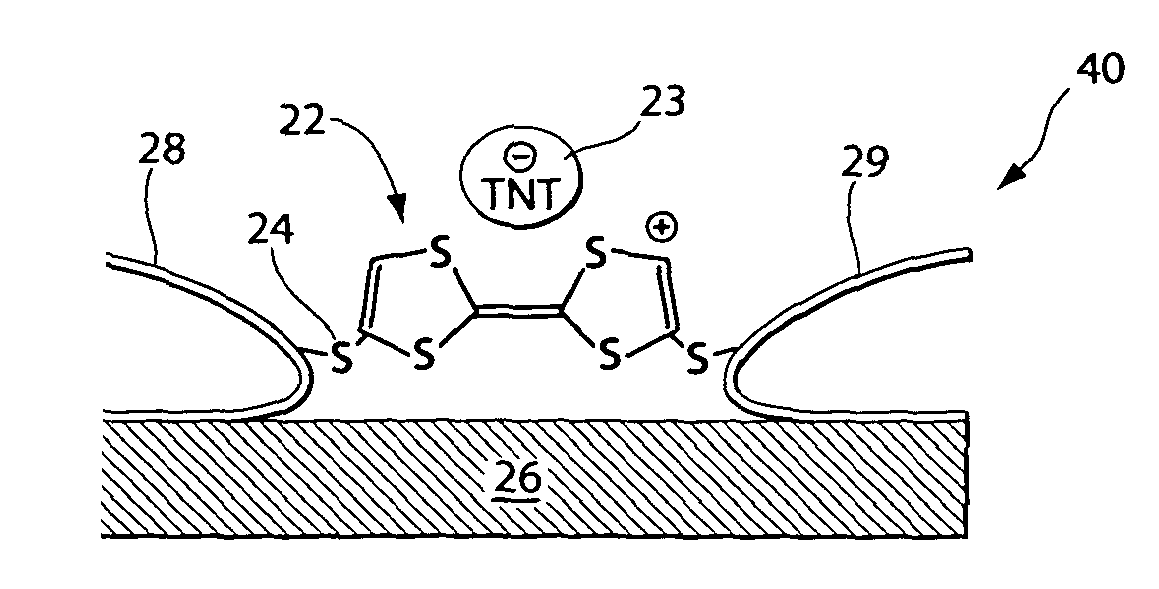
[0029]The present invention has many advantages. A sensor according to various embodiments of the invention is very sensitive towards nitro-containing explosive molecules and is able to detect miniscule amounts of explosives. For example, only one TNT molecule is needed to activate the sensor. A disclosed sensor can be small enough to be located on a chip; to be hand-held or carried; or to be attached, for example, as a badge to a human or other animal. A disclosed sensor comprises a nanometer-size structure that can bind single molecules of explosives with a detectable change in the conductivity and the capacitance of the sensor. A disclosed sensor is capable of mimicking the specificity and sensitivity of an animal's olfactory system for detection of minute amounts of airborne vapors of explosives, for example, that leak from sealed containers, such as mines or bombs. A disclosed sensor is easy to operate and is normally dormant; but in the presence of explosives, its electrical conductivity and capacitance change markedly, whereupon the change can be detected and transmitted as an electronic signal. The present invention thus provides a sensor that can quickly communicate the presence of minute amounts of explosive molecules to remote locations, for example through a computer network.

Problems solved by technology

Although feasible for use outside a laboratory, currently available mass spectrometric systems tend to be an inconvenient size for use in the field.

Method used


Image

  • Molecular sensors for explosives
  • Molecular sensors for explosives
  • Molecular sensors for explosives

Examples


example

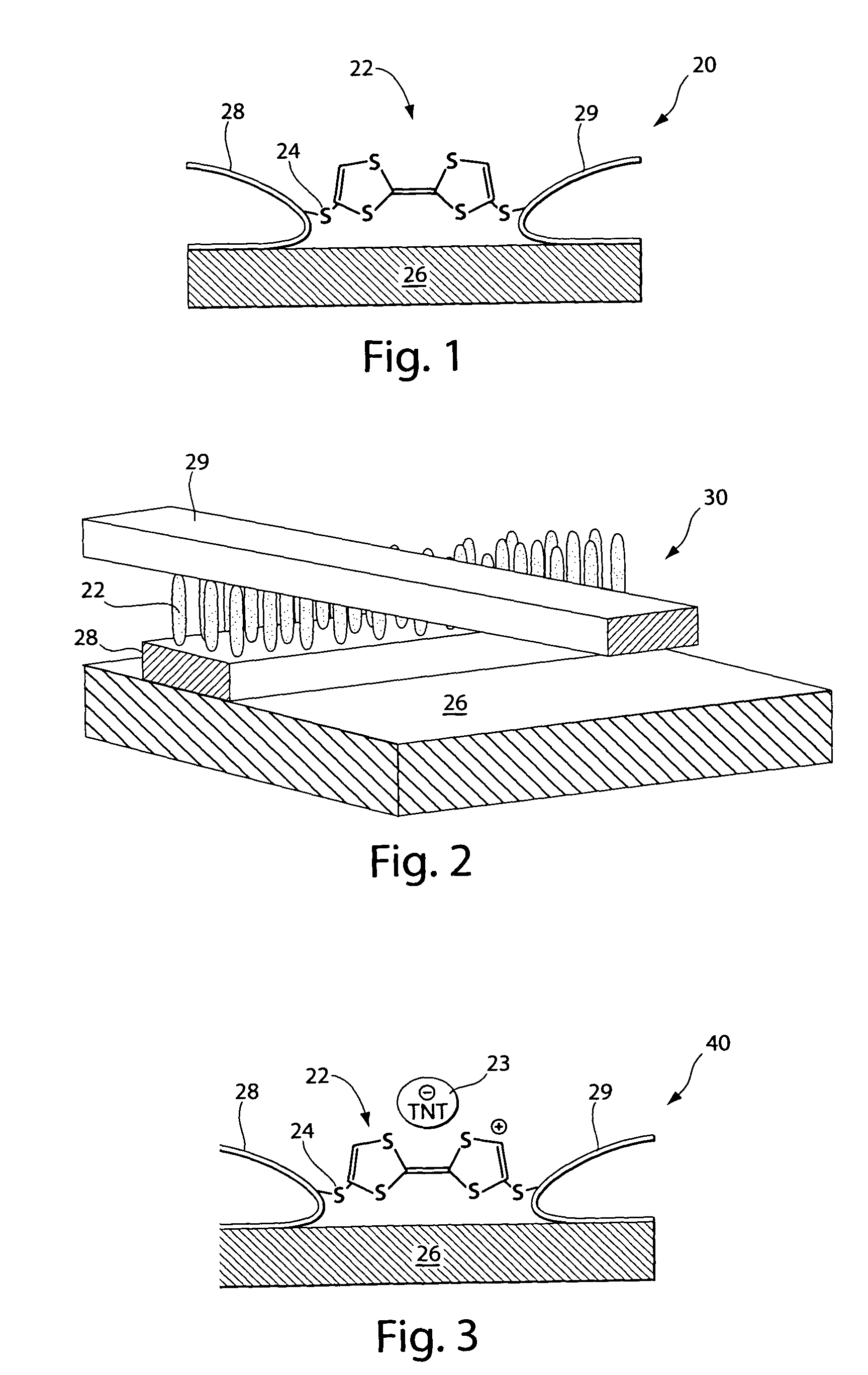
[0078]TTF derivatives containing thiol (SH) pendant groups are prepared from thiolates by deprotection, following the methods described by Becher and co-workers (8). The thiol-protecting groups are 2-cyanoethane. The deprotection is done in situ, namely in place, by the addition of cesium hydroxide monohydrate, dissolved in degassed absolute ethanol. The TTF derivatives are employed as molecular wires and thus contain thiol groups on both rings, to permit bridging between two gold wires that form a gap of from about 1 nanometer (nm) to about 2 nm.

[0079]Formation of gold leads is accomplished by e-beam lithography, according to the method described by Guillorn and co-workers (2), or by break-junction techniques as described by Park and co-workers (4).

[0080]The rest of the operations are best performed in an environmental chamber in the absence of oxygen.

[0081]The substrate, which includes a surface covered with gold electrodes with the proper gaps, is inserted into a solution contain...


PUM

PropertyMeasurementUnit
distanceaaaaaaaaaa
inter-electrode distanceaaaaaaaaaa
diameteraaaaaaaaaa

Abstract

The present invention relates to a molecular sensor for detecting the presence of a target analyte comprising a nitro-containing explosive molecule, the sensor comprising: a support substrate; a pair of electrodes comprising (i) a first electrode and (ii) a second electrode, wherein at least one of (i) and (ii) is at the substrate; an electron donor (ED) molecule capable of forming an electron donor-acceptor (EDA) complex with the nitro-containing explosive molecule; and wherein the ED molecule is disposed between the electrodes and is attached to each electrode by an alligator clip comprising a pendant group, thereby forming a nanojunction between the electrodes; a detection means operably connected to the pair of electrodes, the detection means capable of detecting a change in the electrical resistance or in the capacitance of the sensor when the ED molecule forms an EDA complex with the explosive molecule, the sensor thereby detecting the presence of the explosive molecule. Also disclosed are methods of making and methods of using the sensor.

Description

RELATED APPLICATION[0001]This application claims the benefit of U.S. Provisional Application No. 60 / 577,617 filed on Jun. 7, 2004, the teachings of which are incorporated herein by reference in their entirety.BACKGROUND OF THE INVENTION[0002]A number of methods for detecting explosives are currently available. At present, the most commonly employed method utilizes the sense of smell of an animal such as a dog, pig, or a pouched rat trained for this purpose. The noses of these animals can detect minute amounts of airborne-explosives molecules that leak from sealed containers, such as mines or bombs.[0003]Another approach to explosives detection is based on mass-spectroscopy of air samples. Although feasible for use outside a laboratory, currently available mass spectrometric systems tend to be an inconvenient size for use in the field.[0004]Another technique relies upon nuclear quadrupole resonance (NQR) signals.[0005]Thus the need exists for a fast, reliable, improved sensor for det...

Claims


Application Information

Patent Timeline
Patent Type & Authority Patents(United States)
IPC IPC(8): G01N30/96H01L21/00H01L21/8238H01L21/20G01N27/00G01N27/16
CPCG01N27/126G01N33/0057
Inventor AVIRAM, ARI
Owner AVIRAM ARI
Why Eureka
Try Eureka