

Air handler and purifier
a technology of air handler and purifier, which is applied in the direction of catalyst activation/preparation, metal/metal-oxide/metal-hydroxide catalyst, etc., can solve the problems of terrorist hands, infectious diseases caused by various bacteria, viruses and spores in the hands of terrorists,
- Summary
- Abstract
- Description
- Claims
- Application Information
AI Technical Summary
Problems solved by technology
Method used
Image

Examples
embodiment 1
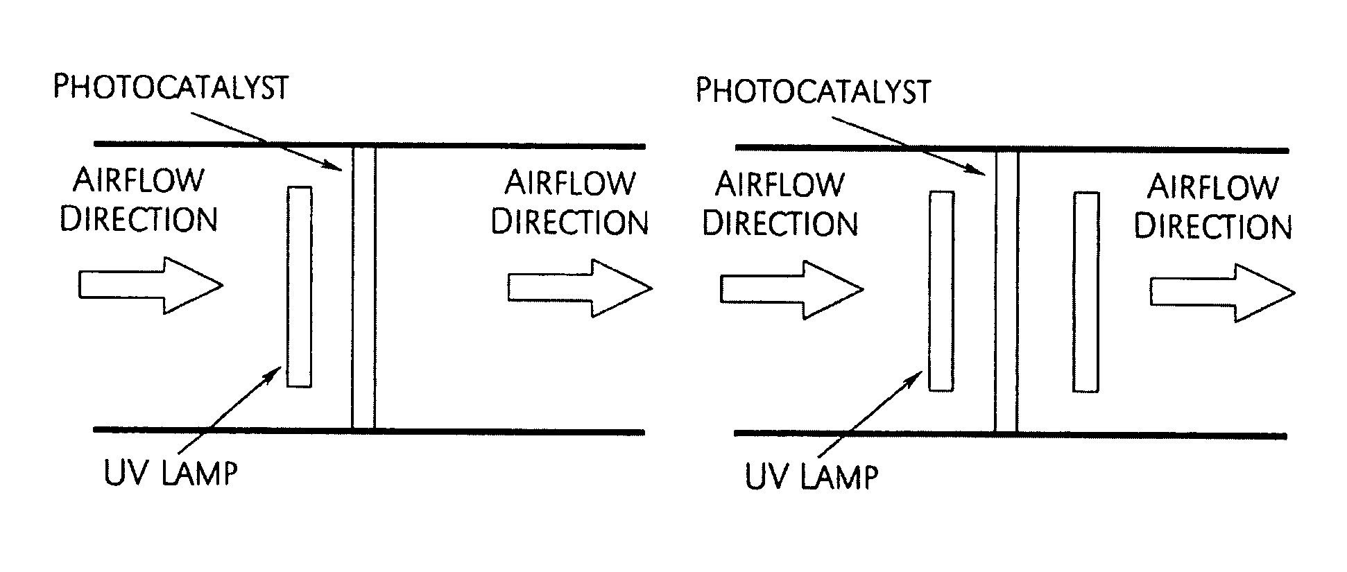
[0012]Flow-through photocatalyst filter for collection / inactivation / decomposition of biological contaminants and decomposition of air contaminants:
[0013]To achieve biological contaminants collection rate of 99.5%, designed is a flow-through filter depicted in FIG. 1. This approach expands the application of the invention to biological contaminants like bacteria, viruses and spores. The new design provides a high collection efficiency for biological air contaminants and increases their contact with the photocatalyst resulting in their subsequent destruction.
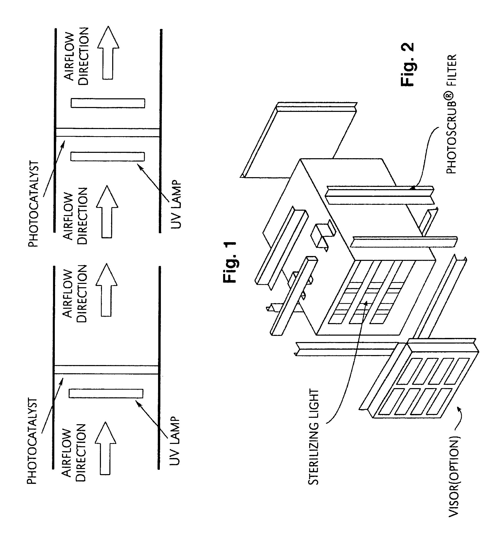
[0014]FIG. 1 illustrates a design of the antimicrobial unit showing two arrangements of UV light sources. This design utilizes a flow-through filter to maximize the contact time of contaminants with the photocatalyst.
[0015]An example of an assembled Biological Elimination Unit (BEU) based on the design depicted in FIG. 1 is shown in FIG. 2.
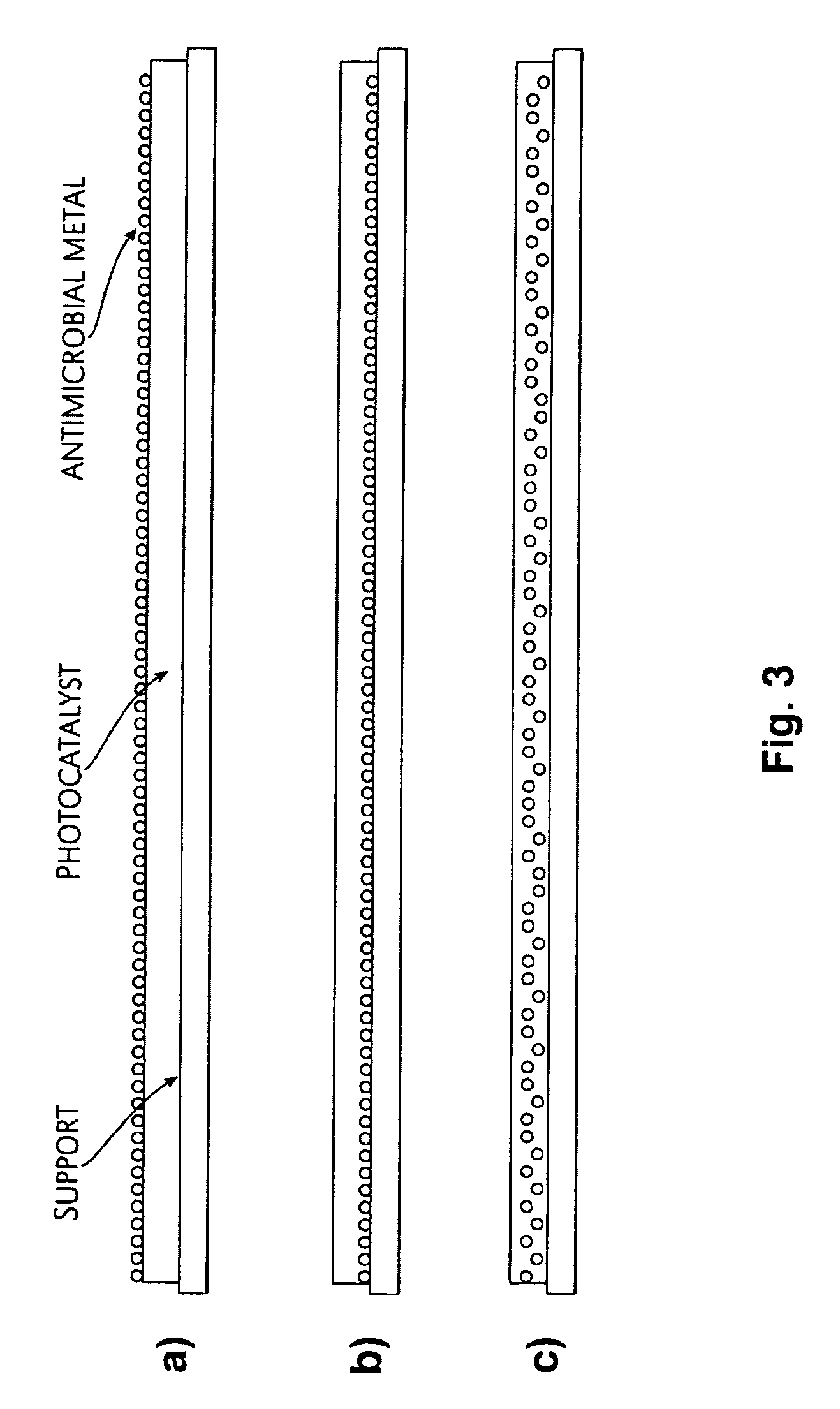
[0016]The material for a flow-through catalyst support may be selected from a variety of cho...
embodiment 3
[0035]Decomposition of the biological material into carbon dioxide and water:
[0036]Procedure: 10 ml Bacillus subtilis solution (107 pcs / ml) were transferred into four glass bottles. The semi-HEPA filter coated with TiO2 was added to the second bottle. The semi-HEPA filter coated with Ag TiO2 was added to the third and fourth bottles (Ag anchored volume in bottle 3:0.42 g / m2; in bottle 4:1.1 g / m2). All bottles were agitated under dark conditions. Another set of four bottles were charged in the same way and subjected to UV irradiation (254 nm) during the agitation. The samples of Bacillus subtilis solutions were collected at the time points of 48, 120, 168 hours for measuring the protein amount using DC Protein Assay (manufactured by Bio-rad Laboratories Inc.). The DC Protein Assay is a reagent used for measuring protein amounts based on the Lowry method. The colorimetric procedure used for the protein concentration determination is shown in FIG. 4 and Table 3. The results of the stud...
embodiment 4
[0043]Design of the photocatalyst capable of high efficiency collection of biological contaminants followed by inactivation of the collected biological material and decomposition to carbon dioxide, water, and, mineral acids / their salts:
[0044]The developed catalyst provides three stage mitigation of the biological threat. In the first stage the biological material (spores, bacteria, viruses) are collected on the surface of the filter (99.98% as demonstrated in Embodiment 1). After the biological material is collected, the catalyst, UV light and silver together provide efficient inactivation of the living organisms (99.95% in 1 hour as demonstrated in Embodiment 2). After that, the catalyst still acts on the collected and neutralized material and fully decomposes the material into carbon dioxide, water, and mineral acids / mineral salts (Embodiment 3). If any organic contaminants (cigarette smoke, sick-house syndrome, acetone, acetaldehyde, etc.) are present in the air stream, they will...
PUM
| Property | Measurement | Unit |
|---|---|---|
| Surface area | aaaaa | aaaaa |
| Ionicity | aaaaa | aaaaa |
Abstract
Description
Claims
Application Information