Process and apparatus for depositing a ceramic coating

a technology of ceramic coating and process, applied in the field of coating processes, can solve the problems of difficult to produce ceramic coatings having uniform and desired composition, and achieve the effect of promoting stable porosity within the coating and lowering thermal conductivity

Inactive Publication Date: 2010-11-02
GENERAL ELECTRIC CO
View PDF2 Cites 3 Cited by
  • Summary
  • Abstract
  • Description
  • Claims
  • Application Information

AI Technical Summary

Benefits of technology

[0010]According to one aspect of the invention, the process is particularly suited for use when the oxide of the carbide compound element has a vapor pressure that is significantly different from the oxide compounds. If a YSZ coating is to be deposited, particularly notable examples of such oxides include ytterbia, neodymia, and lanthana, each of which has a sufficient absolute percent ion size difference relative to zirconium ions to produce significant lattice strains that promote lower thermal conductivities. As a result of their significantly different vapor pressures, it is difficult to produce a ceramic coating having a uniform and desired composition by simultaneously evaporating one or more ingots of YSZ and any one or more of these oxides. In accordance with this invention, these oxides can be codeposited with YSZ by evaporating their corresponding carbides, i.e., YbC2, NdC2, and LaC2, which dissociate during evaporation to form the oxide if sufficient oxygen is present within the vapor cloud to oxidize the metal dissociated from the carbide. Furthermore, the process of this invention also advantageously co-deposits one or more carbon-based constituents that also evolve from evaporation of the carbide(s), promoting stable porosity within the coating.

Problems solved by technology

As a result of their significantly different vapor pressures, it is difficult to produce a ceramic coating having a uniform and desired composition by simultaneously evaporating one or more ingots of YSZ and any one or more of these oxides.

Method used


Image

  • Process and apparatus for depositing a ceramic coating
  • Process and apparatus for depositing a ceramic coating

Examples


Embodiment Construction

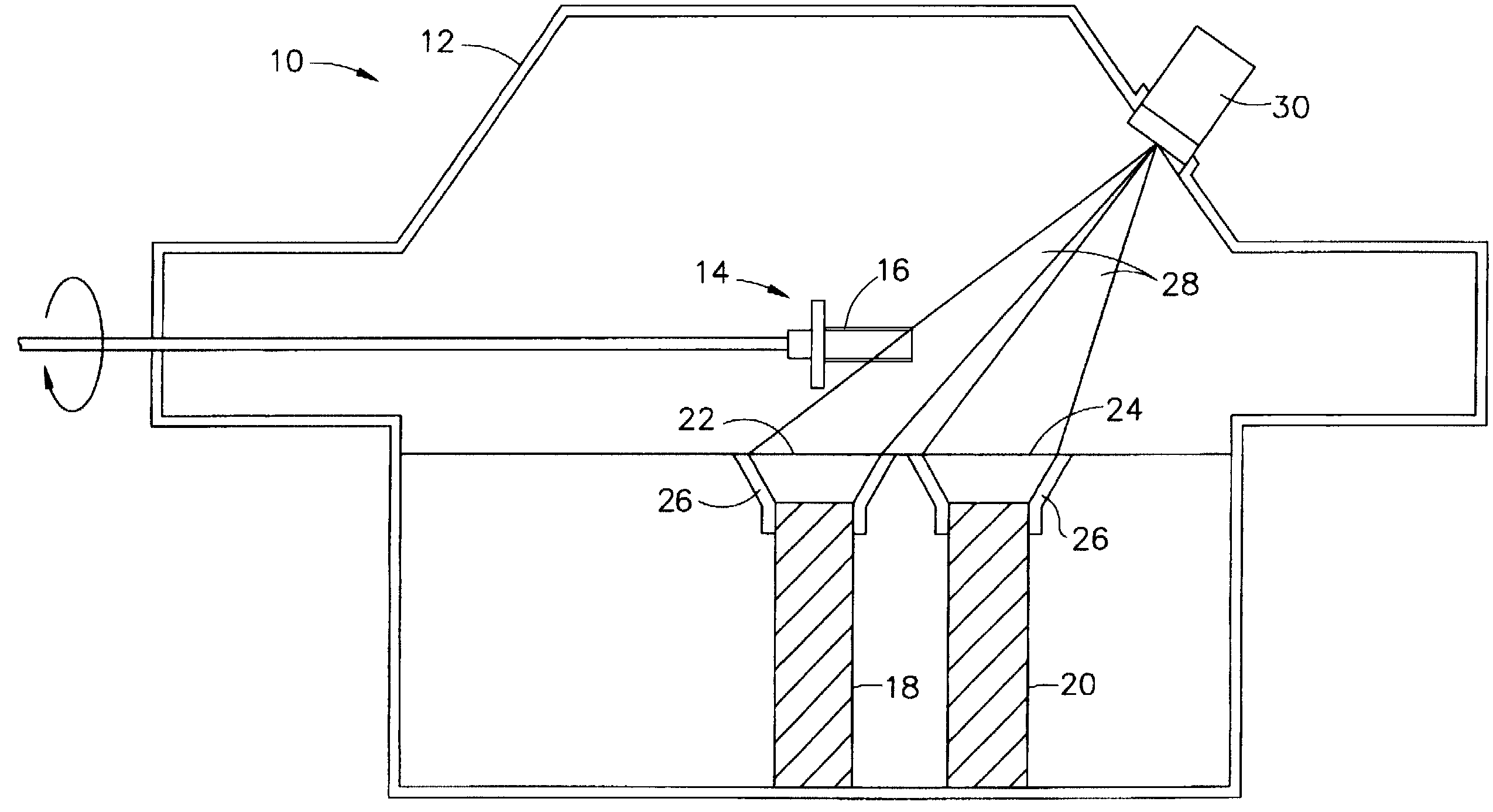
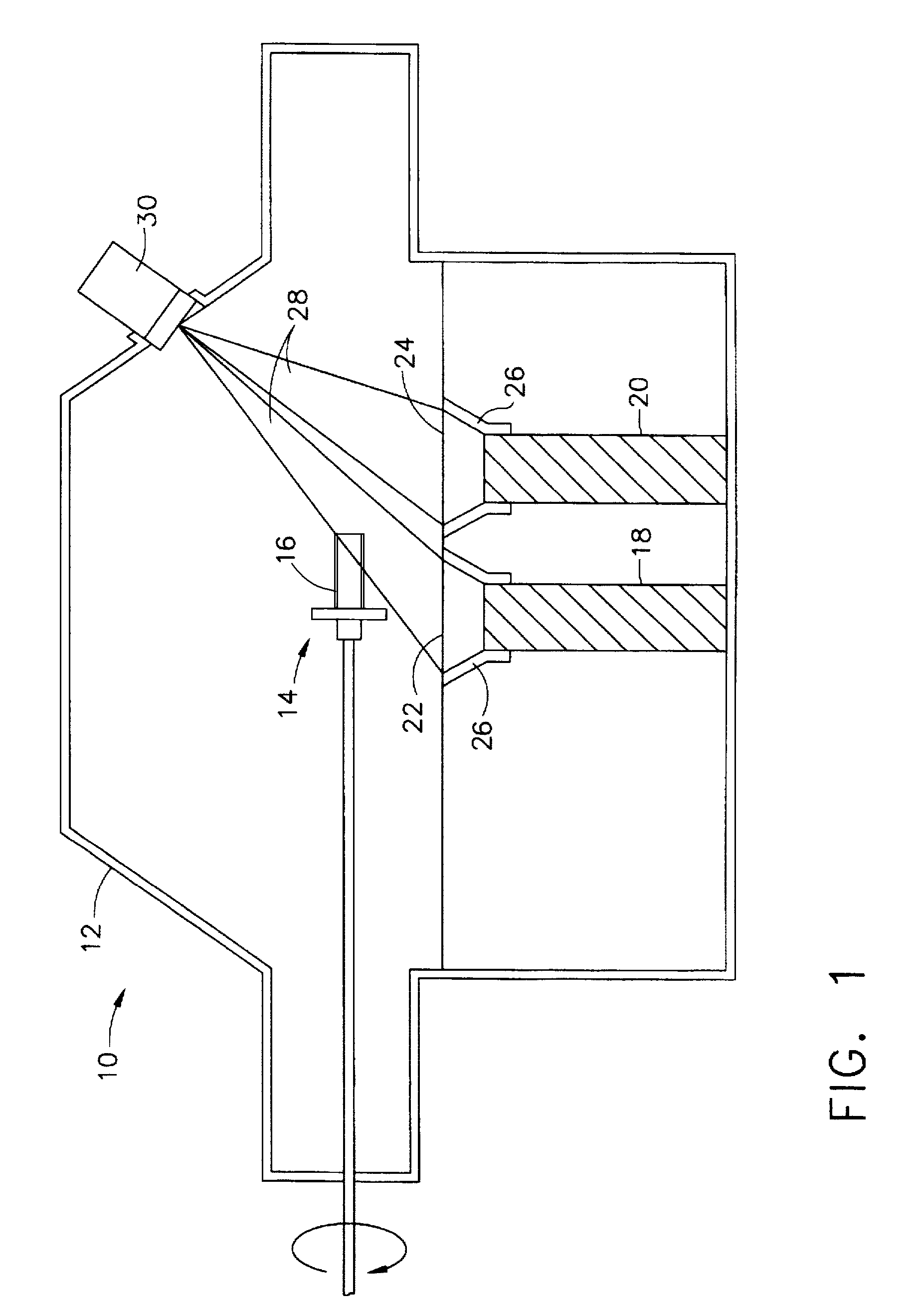
[0013]The present invention is generally applicable to components subjected to high temperatures, and are therefore often formed of a superalloy material. The advantages of this invention are particularly applicable to TBC's for gas turbine engine components, such as the high and low pressure turbine nozzles and blades, shrouds, combustor liners and augmentor hardware. However, the teachings of this invention are more generally applicable to processes and apparatuses for depositing a ceramic coating. To provide the required thermal protection for a particular component, TBC's are typically deposited to a thickness of about 75 to about 300 micrometers, though lesser and greater thicknesses are foreseeable. Adhesion of the TBC to a superalloy substrate is typically promoted with the use of a bond coat, preferably an aluminum-rich composition such as an overlay coating of beta-phase NiAl intermetallic or MCrAlX alloy or a diffusion aluminide coating, though it is foreseeable that other...


PUM

PropertyMeasurementUnit
thicknessesaaaaaaaaaa
temperatureaaaaaaaaaa
melting pointsaaaaaaaaaa

Abstract

A process and apparatus for depositing a ceramic coating, such as a thermal barrier coating (TBC) for a gas turbine engine component. The process deposits a coating whose composition includes multiple oxide compounds and a carbon-based constituent, e.g., elemental carbon, carbides, and carbon-based gases. The process uses at least one evaporation source to provide multiple different oxide compounds and at least one carbide compound comprising carbon and an element. The evaporation source is evaporated to produce a vapor cloud that contacts and condenses on the component surface to form the ceramic coating, and particularly so that the coating comprises the oxide compounds, an oxide of the element of the carbide compound, and the carbide compound and / or a carbon-containing gas. The process is carried out with an apparatus comprising a coating chamber in which the evaporation source is present, and a device for evaporating the evaporation source.

Description

BACKGROUND OF INVENTION[0001]1. Field of the Invention[0002]The present invention generally relates to coating processes. More particularly, this invention is directed to a physical vapor deposition process and apparatus for depositing ceramic coatings containing multiple oxides and elemental carbon and / or a carbon-based gas.[0003]2. Description of the Related Art[0004]Certain components of the turbine, combustor and augmentor sections of a gas turbine engine are typically protected from their harsh thermal environments by a thermal barrier coating (TBC) formed of a ceramic material. Various ceramic materials have been proposed for TBC's, the most notable of which is zirconia (ZrO2) that is partially or fully stabilized by yttria (Y2O3). Binary yttria-stabilized zirconia (YSZ) is widely used as a TBC material because of its high temperature capability, low thermal conductivity and erosion resistance in comparison to zirconia stabilized by other oxides. YSZ is also preferred as a res...

Claims


Application Information

Patent Timeline
Patent Type & Authority Patents(United States)
IPC IPC(8): C23C14/30C23C14/06C23C14/08C23C16/00
CPCC23C14/06C23C14/08
Inventor DAROLIA, RAMGOPALSPITSBERG, IRENEBOUTWELL, BRETT ALLEN ROHRER
Owner GENERAL ELECTRIC CO
Why Eureka
Try Eureka