Magnetic bearing device and method

a magnetic bearing and magnetic technology, applied in non-electric variable control, process and machine control, instruments, etc., can solve the problems of increasing energy consumption, unable to detect the displacement of rotating pieces, and generating copper loss in electromagnet coils, so as to reduce costs, save energy, and waste no redundant energy

Inactive Publication Date: 2010-11-09
EBARA CORP
View PDF15 Cites 14 Cited by
  • Summary
  • Abstract
  • Description
  • Claims
  • Application Information

AI Technical Summary

Benefits of technology

[0024]In the aspect (1) of the present invention, no bias current flows in the electromagnet so there is no need for a circuit to supply a bias current. Therefore, along with lowering costs there is also the advantage that the electromagnet coil wastes no redundant energy so an energy-saving magnetic bearing device can be provided. The magnetic force is applied to the magnetic piece from either one of the opposing magnets so the magnetic force applied to the magnetic piece can be easily estimated. The excitation current only flows in either one of the opposing magnets so energy can be saved. Moreover, a ripple current is generated by applying an alternating voltage oscillating at the same frequency as the carrier frequency of the PWM driver. The change in inductance of the electromagnet can be detected from this ripple current even if the electromagnet excitation current is near zero in a DC component, so that the displacement of the magnetic piece can be detected from this change in inductance.
[0025]In another aspect (2) of the present invention, the alternating current transfer means is composed of a coil and capacitor connected in series, and can therefore be easily constructed using a commercially available coil and capacitor.
[0026]In yet another aspect (3) of the present invention, the displacement detection error caused by the effect of a change in magnetic properties due to the change of the excitation current in the electromagnet, in other words a change of inductance of the magnet due to the excitation current, can be estimated from the electromagnet's excitation current. The displacement can therefore be detected with good accuracy by removing the error differential from the displacement detection signal.
[0027]In still another aspect (4) of the present invention, the displacement detection error caused by the effect of a change in magnetic properties due to the change of the excitation current in the electromagnet, in other words a change of inductance of the magnet due to the excitation current, can be estimated from a signal output from a compensation means. The displacement can therefore be detected with good accuracy by removing the error differential from the displacement detection signal.
[0028]In a further aspect (5) of the present invention, the magnetic bearing device includes a linearization means for making the relation between the magnetic force exerted on the magnetic piece and the excitation current of the electromagnet linear. An electrical current control signal can therefore be sent to the driver to make the magnetic force applied to the magnetic piece linear versus the displacement signal obtained from the displacement detection means so that a simple linear system can be established for the magnetic bearing device.
[0029]In a yet further aspect (6) of the present invention, the compensation means, or the linearization means, or the compensation means and linearization means are structured to acquire an output by digital processing. The characteristics of the compensation means and linearization means can therefore be easily programmed via a digital processing means such as DSP (Digital Signal Processor) to eliminate the bothersome task of building-and-assembling circuits and soldering work and to also allow those characteristics to easily change.

Problems solved by technology

However, forming a linear relation between the excitation current in the electromagnet and the magnetic force exerted on the rotating piece by applying a DC bias to the electromagnet, constantly generates a copper loss in the electromagnet coil.
This copper loss generates redundant heat in the magnetic bearing and therefore causes energy consumption to increase.
This driver utilizes a flywheel diode and so can only allow current flow to the electromagnet in one direction, and no ripple current is generated in the vicinity of the region where the electromagnet current is zero so detecting the rotating piece displacement is impossible.
However, the Background Art failed to provide a sensor-less magnetic bearing with zero bias magnetic bearing of a method of eliminating the flow of a bias current in the electromagnet to improve power consumption and to lower heat generation.

Method used


Image

  • Magnetic bearing device and method
  • Magnetic bearing device and method
  • Magnetic bearing device and method

Examples


first embodiment

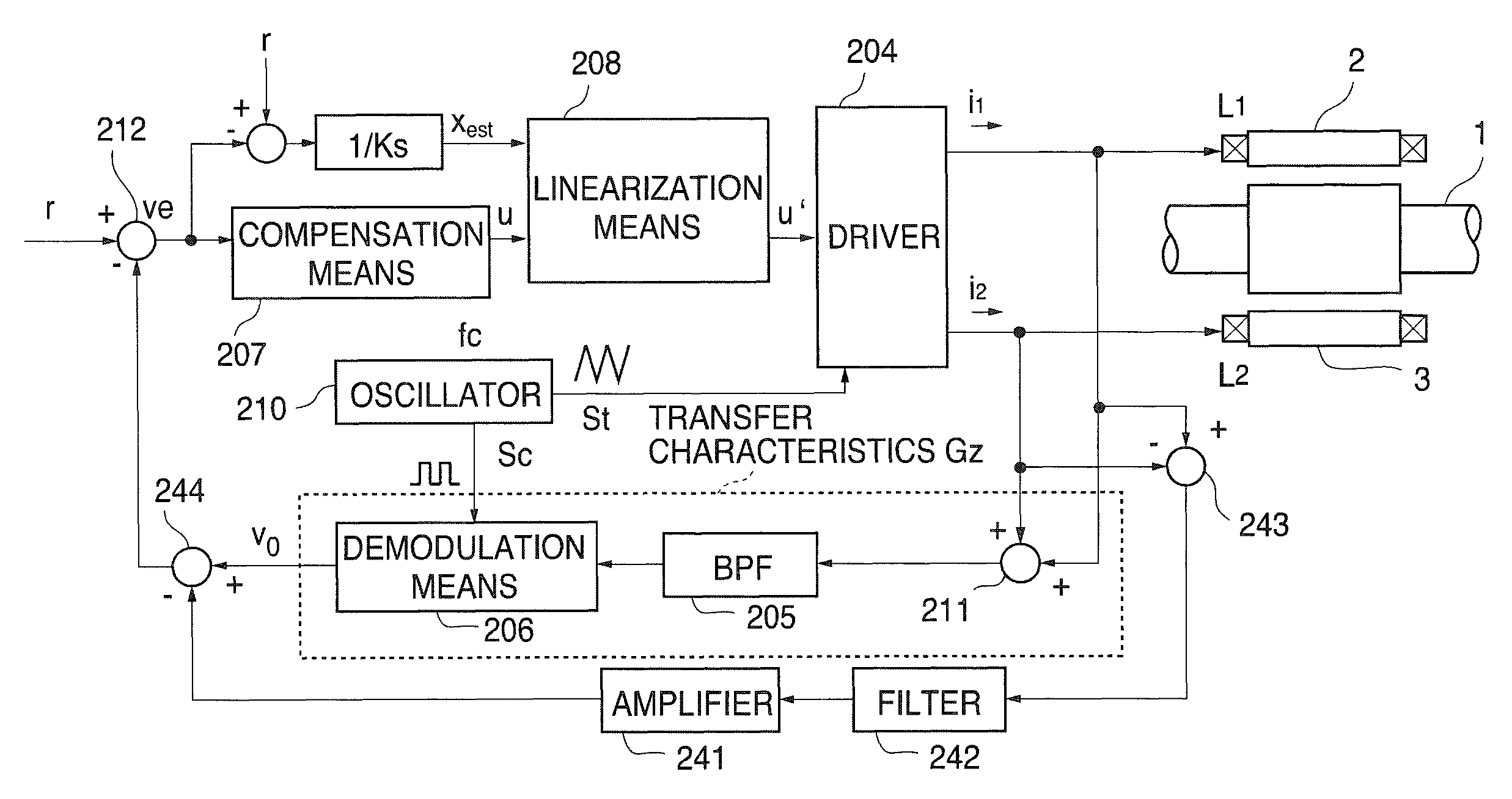
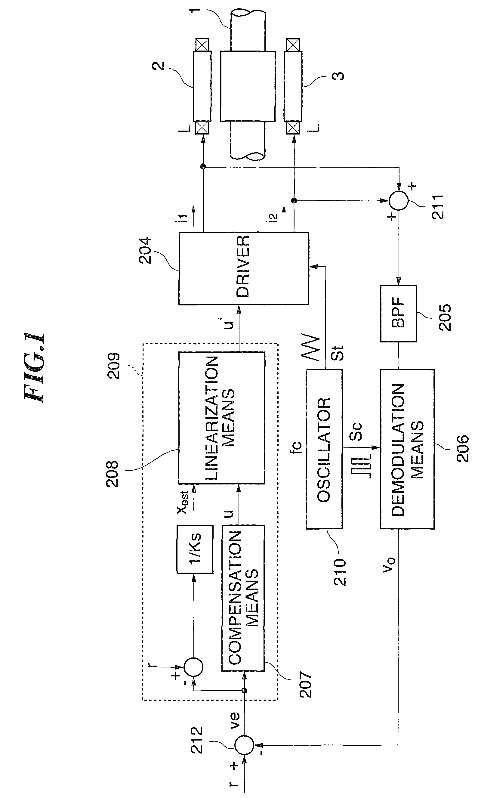
[0139]As shown in FIG. 1, the magnetic bearing device of the first embodiment, detects the excitation current i1 and excitation current i2 and by allowing the sum of their respective signals to pass through a band-pass filter 205 whose center frequency is the carrier frequency fc, removes the control current ic of formula (3), and extracts the ripple current component or in other words, the displacement information component ir1−ir2. This displacement information component is obtained as an AM modulation signal equal to the carrier frequency fc, versus the displacement of the rotor 1, and is demodulated by the demodulation means 206, to obtain the displacement signal v0. The demodulation means 206 demodulates the displacement information component of the AM modulation signal according to the pulse signal Sc of a frequency equal to the PWM carrier frequency fc obtained from the oscillator 210.

[0140]The displacement signal v0 obtained by the demodulation means 206 is fed back and the ...

second embodiment

[0185]the present invention was described, however, the present invention is not limited to the above embodiments, and various changes and adaptations are possible within the scope of the patent claims as well as the within the scope of the technical concepts in the specifications and drawings.


PUM


Abstract

An energy-saving magnetic bearing device with no bias current for making the relation between the excitation current and the magnetic force of the electromagnet linear is provided. In a magnetic bearing device for supporting a rotor 1 serving as the magnetic piece in a levitating state allowing free rotation at a specified position by the magnetic force of a pair of electromagnets 2, 3, the electromagnets 2, 3 are constituted to interpose the rotor 1 and face each other. A driver 204 is a PWM (pulse width modulation) type driver for controlling the excitation current in the electromagnets 2, 3 by modulating the pulse width of a voltage driven at a specified carrier frequency fc, and includes a resonator means for electrically resonating at a frequency equal to the carrier frequency fc. When an excitation current flows in either one of the pair of opposing electromagnets 2, 3, then the other magnet is regulated so that the DC component in the electromagnet excitation current is zero, and a voltage is applied via the resonator means to the electromagnet whose DC component in the excitation current is discharged to zero.

Description

TECHNICAL FIELD[0001]The present invention relates to a magnetic bearing device and a magnetic bearing method for detecting the displacement of a magnetic piece by the change in impedance of the electromagnet for supporting the magnetic piece in a levitating state, and controlling the magnetic force of that electromagnet to support the magnetic piece in a specified position, and more particularly to a magnetic bearing device and a magnetic bearing method suitable for energy-saving.[0002]The present invention further relates in particular to a magnetic bearing device and a magnetic bearing method including a displacement detection means for detecting with high accuracy the displacement of a magnetic piece by the change in impedance of the electromagnet.BACKGROUND ART[0003]Magnetic bearing devices utilizing magnetic force for non-contact support of a rotating piece are widely used in rotating equipment in the Background Art such as turbo molecular pumps that require a rotating piece b...

Claims


Application Information

Patent Timeline
Patent Type & Authority Patents(United States)
IPC IPC(8): H02K7/09F16C39/00
CPCF16C32/0448F16C32/0457F16C2360/45
Inventor BARADA, TOSHIMITSUYOSHIDA, TOSHIYA
Owner EBARA CORP
Why Eureka
Try Eureka