Phase locked loop, voltage controlled oscillator, and phase-frequency detector

a voltage control and phase lock technology, applied in the field of electronic circuits, can solve problems such as interference problems with adjacent transmission channels and reference clock feedthroughs

Active Publication Date: 2010-11-09
MEDIATEK INC +1
View PDF3 Cites 32 Cited by
  • Summary
  • Abstract
  • Description
  • Claims
  • Application Information

AI Technical Summary

Problems solved by technology

Spurs in the reference signal also present an issue for conventional charge pump PLLs, where pulse-width comparison is performed in the phase detector, leading to interference problems to adjacent transmission channels.
The reference clock feedthrough for conventional charge pump PLLs has always been an issue, wherein attempts have been made to minimize the reference spurs by: a charge transfer technique to spread out the momentary signal surge over a period; an analog phase detector using current-mode logic to reduce swing; a compensated charge-pump design to balance the device mismatch; and a distributed phase detector to avoid abrupt changes on the control voltage.
However, none of the approaches eliminates pulse generation, so the control line ripple is never entirely removed.

Method used


Image

  • Phase locked loop, voltage controlled oscillator, and phase-frequency detector
  • Phase locked loop, voltage controlled oscillator, and phase-frequency detector
  • Phase locked loop, voltage controlled oscillator, and phase-frequency detector

Examples


Embodiment Construction

[0034]The following description is of the best-contemplated mode of carrying out the invention. This description is made for the purpose of illustrating the general principles of the invention and should not be taken in a limiting sense. The scope of the invention is best determined by reference to the appended claims.

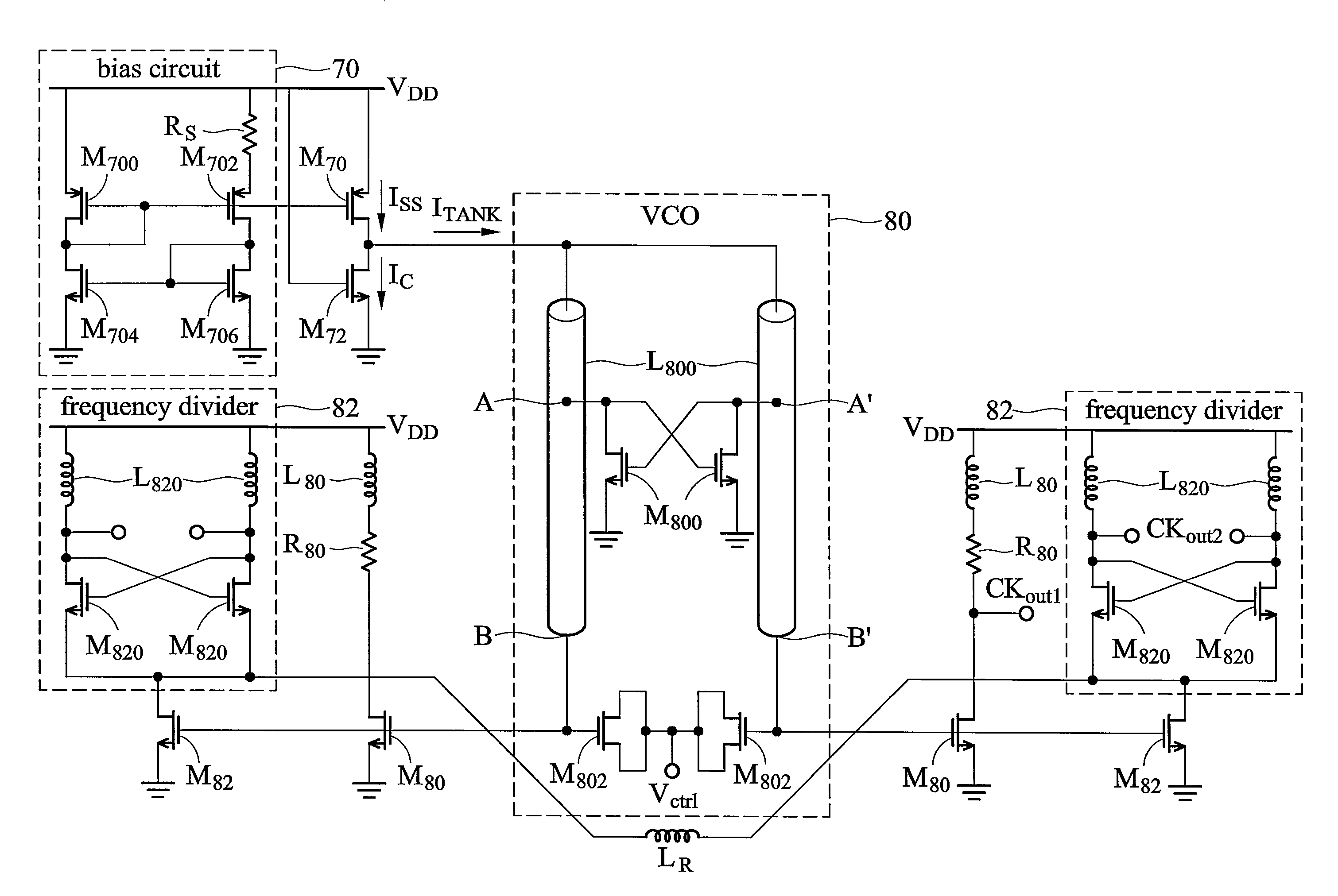
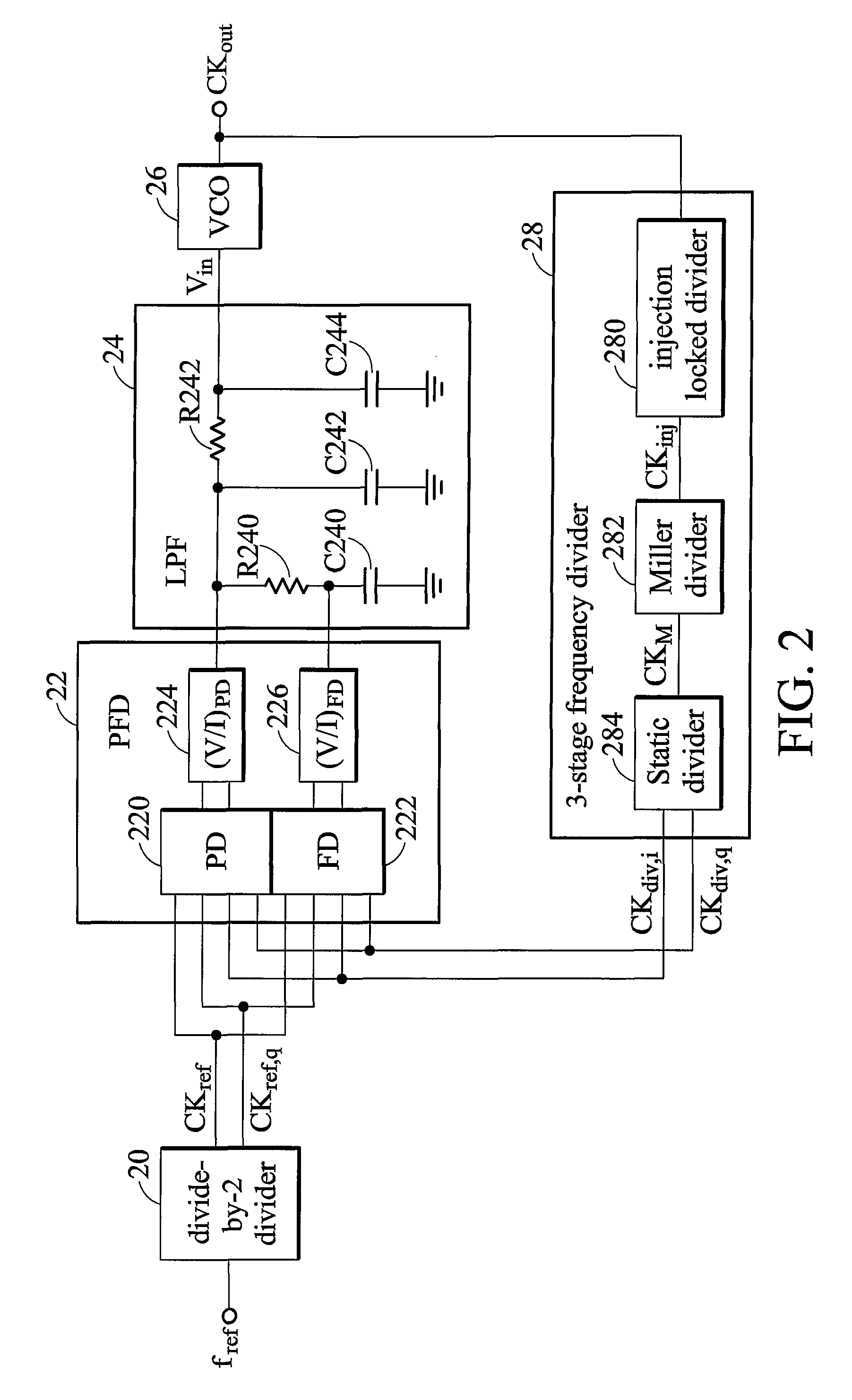
[0035]FIG. 2 is a block diagram of an exemplary Phase-Locked Loop (PLL) according to the invention, comprising divide-by-2 divider 20, phase-frequency detector (PFD) 22, loop filter 24, voltage controlled oscillator (VCO) 26, and 3-stage frequency divider 28. Divide-by-2 divider 20 is coupled to phase-frequency detector 22. Phase-frequency detector 22, loop filter 24, voltage controlled oscillator 26, and 3-stage frequency divider 28 are coupled in a loop.

[0036]PLL 2 is implemented to produce a clock signal with low jitter and wide operating range. Divide-by-2 divider 20 provides quadrature reference inputs CKref,i, CKref,q. Phase-frequency detector 22 receives referen...


PUM


Abstract

A phase locked loop, voltage controlled oscillator, and phase-frequency detector are provided. The phase locked loop comprises a phase-frequency detector (PFD), a loop filter (LF), a voltage controlled oscillator (VCO), and a 3-stage frequency divider. The PFD receives a reference signal and a feedback signal to determine phase and frequency errors. The LF), coupled to the phase-frequency detector, filters the phase and frequency errors to generate a control voltage. The VCO, coupled to the loop filter, generates a VCO output signal according to the control voltage. The 3-stage frequency divider, coupled to the voltage controlled oscillator, divides the frequency of the VCO output signal 3 times to generate the feedback signal.

Description

CROSS REFERENCE[0001]This application claims the benefit of U.S. provisional application Ser. No. 60 / 952,609 filed Jul. 30, 2007, the subject matter of which is incorporated herein by reference.BACKGROUND OF THE INVENTION[0002]1. Field of the Invention[0003]The invention relates in general to electronic circuits, and in particular, to electronic circuits of phase locked loops (PLL), voltage controlled oscillators (VCO), and phase-frequency detectors (PFD).[0004]2. Description of the Related Art[0005]As device size scales down, CMOS devices are achieving higher operating speeds. The low power consumption and high circuit integration of miniaturized devices, along with the improvement of broadband techniques, make CMOS technology attractive in realizing ultra-fast phase locked loop (PLL) circuits.[0006]FIG. 1 is a block diagram of a conventional PLL, comprising phase-frequency detector 10, charge pump circuit 12, voltage controlled oscillator (VCO) 14, and divider 16. Phase-frequency ...

Claims


Application Information

Patent Timeline
Patent Type & Authority Patents(United States)
IPC IPC(8): H03B5/12
CPCH03L7/085H03L7/099H03L7/113H03L7/18H03L7/191
Inventor LEE, JRILIU, MING-CHUNG
Owner MEDIATEK INC
Why Eureka
Try Eureka