Furnace panel leak detection system

a technology for detecting system and furnace, which is applied in the direction of furnaces, combustion types, and failure to meet the requirements of combustion, etc., can solve the problems of large volume of cooling water entering the furnace, frequent leakage of furnace wall panels, and cumbersome procedures

Active Publication Date: 2010-11-16
BERRY METAL
View PDF18 Cites 19 Cited by
  • Summary
  • Abstract
  • Description
  • Claims
  • Application Information

AI Technical Summary

Benefits of technology

[0016]The present invention provides a furnace panel leak detection system that includes several types of redundant coolant panel leak detection mechanisms which continuously and actively monitor and report the condition of the panel itself or the coolant fluid that flows therethrough. In this way, several layers or tiers of protective redundancy are built into the system that serve to provide instantaneous information about the furnace panel that may be necessary for quick shut down of the coolant system flow or furnace operation.
[0018]The system further desirably allows local or remote monitoring, diagnosis and troubleshooting of potential problems with furnace panels that exhibit abnormal performance characteristics.

Problems solved by technology

Because of the high temperature and severe reaction conditions inside many industrial furnaces, furnace wall panels frequently develop leaks.
However, isolating the leak to the particular cooling circuit in which the leak is located may be a cumbersome procedure when the cooling system contains several cooling circuits, as is often the case in modern industrial furnaces.
Failure to do so may cause large volumes of cooling water to enter into the furnace.
Water that becomes trapped under the molten metal quickly turns to steam resulting in a rapid expansion and subsequent explosion.
These catastrophic events, though rare, can cause massive amounts of damage to the furnace and its surroundings.
Alternatively, when the water in the leaky cooling member is at a pressure lower than the furnace internal gas pressure, failure to rapidly detect a leak may cause the loss of large amounts of furnace gas, often combustible gas, into the cooling circuit which may create serious safety problems.
In addition, furnace gas entering the cooling system could be drawn into the pumping system and damage the pumps.
Moreover, furnace gas leaking into, or steam generated in, a cooling plate that has or is about to fail may generate chain reaction damage in downstream cooling members in the circuit.
That is, the temperature of the cooling fluid in downstream cooling members rises, thereby compromising the effectiveness of the cooling fluid in downstream cooling members which, in turn, may potentially cause a leak in one or more of those downstream members.
The failure or simple delay in operation of a such a single-tier monitoring system may result in a water leak with potential attendant equipment damage and possible personal injury.
While an improvement over the single-tier furnace panel leak detection systems described above, the multiple-tier system disclosed in U.S. Pat. No. 4,207,060 nevertheless suffers from certain disadvantages.
For example, by their very nature, check valves present obstructions in the fluid line which cause sudden spike-like pressure drops in the fluid circuit when the check valve opening pressure is overcome.
Together, these variables at least temporarily affect the reliability of the data recorded by and observed from the panel outlet temperature and flow sensors.
Moreover, the default “off” position of check valves tends to promote the buildup of foreign solid particles which could ultimately block the fluid circuit.
Should clogging or mechanical failure occur in either the panel inlet or outlet check valve, water flow through the panel will be reduced or stopped, thereby leading to a rapid rise in panel temperature and possible harm to the panel, the furnace and the furnace surroundings.
In addition, the provision of the coolant flow check valves at the outlets of the panels can cause water hammer damage to the coolant water return line into which they are discharged because of the sudden actuation nature typical of check valves.
Additionally, the presence of a single water temperature sensor, a single water pressure sensor and a single water flow sensor in the cooling water supply line upstream of the panels, i.e., before the coolant water reaches any of the panels, cannot provide an operator of the furnace with optimally accurate readings of the coolant water temperature, pressure and flow rate as it enters each panel.
The significance of this feature is that the downstream temperature and flow sensors compare panel water temperature versus coolant water temperatures and flows that may be rather distant therefrom, hence producing less than desirable comparative results.
Still further, the pressure relief valves at the outlets of the panels provide no meaningful data or information about conditions within the panels.
As such, they are prone to clogging.
Furthermore, they do not provide the furnace operator with real-time coolant panel outlet pressure data that may be useful in understanding and possibly anticipating malfunctions that might occur in a furnace panel during operation.
Welds are notorious locations for cracks that may lead to water leakage.
This presents a problem at plant locations where coolant water is in limited supply and / or available at premium cost.
However, manual monitoring is undesirable because of its inherent dependence upon the diligence and competence of a human operator coupled with the reliability of the equipment used to make the pressure measurements.

Method used


Image

  • Furnace panel leak detection system
  • Furnace panel leak detection system
  • Furnace panel leak detection system

Examples


Embodiment Construction

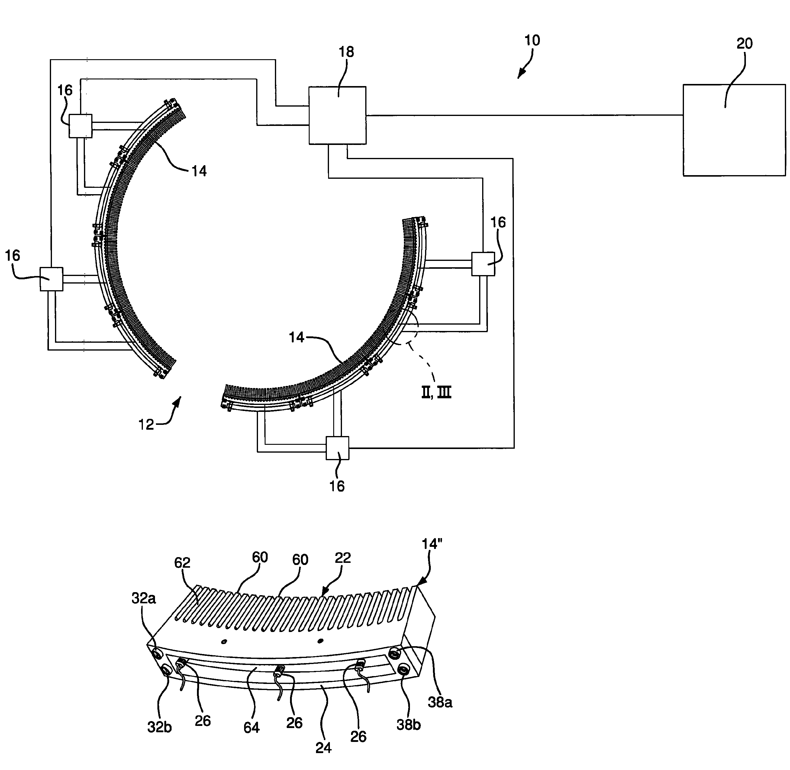
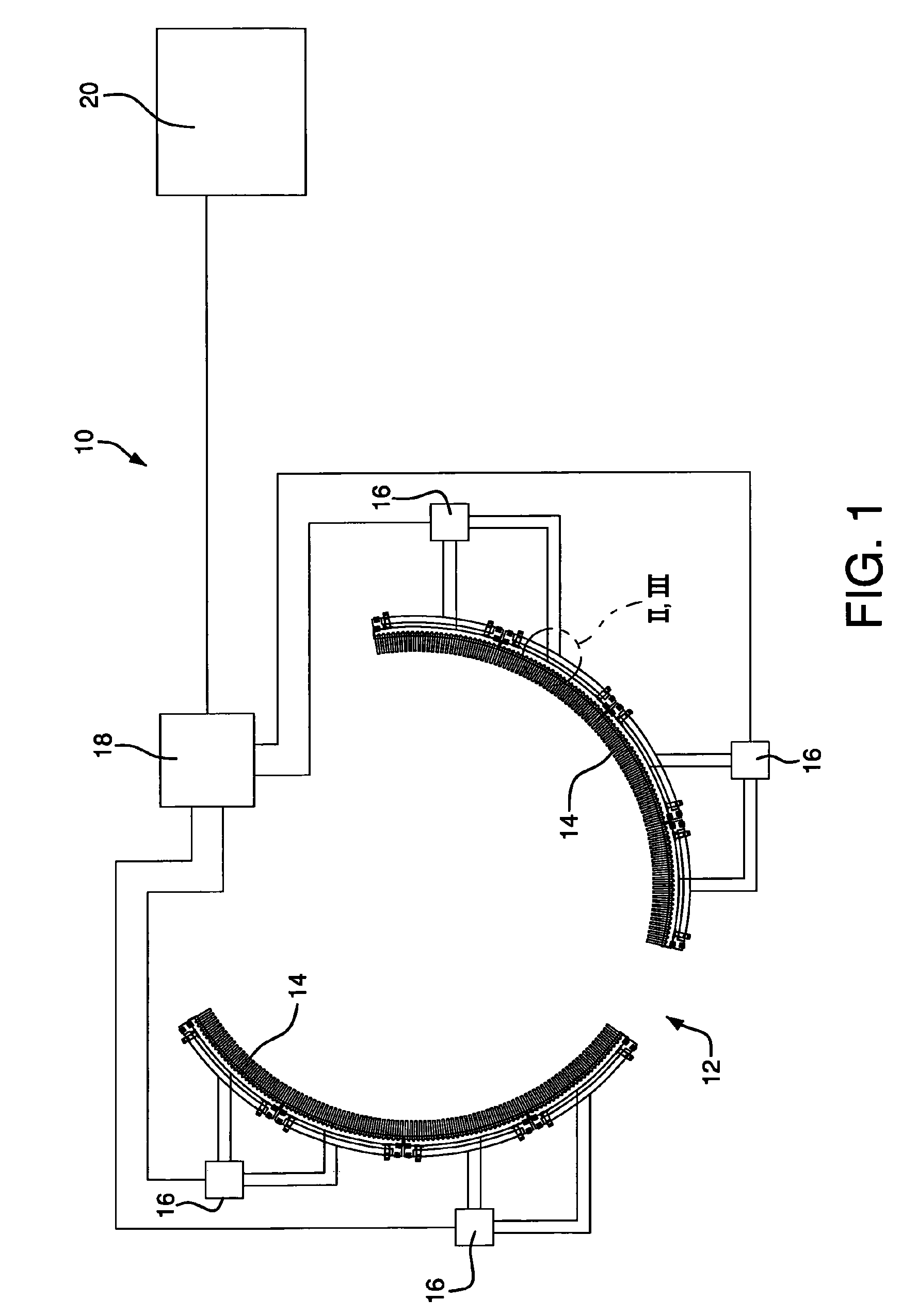
[0027]Referring to the drawings wherein like or similar references indicate like or similar elements throughout the several views, there is shown in FIG. 1 a furnace panel fluid coolant leak detection system according to the present invention, identified generally by reference numeral 10. The system includes a high energy, typically industrial, furnace 12 such as a metal smelting furnace, a blast furnace, an EAF or the like. Furnace 12 is shown in top plan view in FIG. 1 and includes a plurality of fluid-cooled wall panels 14, described in greater detail hereinafter, several of which are omitted for clarity of illustration. A typical furnace may be about 15-30 feet in diameter and may comprise from as few as about 4 panels to as many as about 40 panels, although the furnace dimensions and number of panels may vary and will be dependent upon the requirements of the furnace installation.

[0028]System 10 further comprises a plurality of electrical junction boxes 16 in electrical communi...


PUM


Abstract

A furnace panel leak monitoring and control system for fluid-cooled panels in high temperature industrial furnaces such as, for example, smelting furnaces, blast furnaces and electric arc furnaces. The system performs at least two and up to four functions simultaneously. At minimum, the system includes one or more temperature sensors received within the body of the panel to monitor temperature within the metal of the panel itself, and pressure sensors installed proximate the inlet and outlet of each panel coolant fluid circuit, which circuits are preferably periodically automatically tested, to check for leaks in the coolant circuits. In addition, the system preferably includes temperature and flow sensors for monitoring the furnace panel coolant circuit(s) for temperature and flow fluctuations, respectively, which may be indicative of leaking cooling circuits. The system triggers visual and / or audible alarms to alert a human operator of an apparent coolant fluid leak situation.

Description

FIELD OF THE INVENTION[0001]The present invention relates in general to furnace apparatus and in particular to a system including method and apparatus for detecting leaks in fluid-cooled panels and coolers for industrial furnaces such as metal smelting furnaces, blast furnaces, electric arc furnaces (EAFs) or the like.BACKGROUND OF THE INVENTION[0002]Many industrial furnaces such as smelting furnaces, blast furnaces, EAFs and the like typically have shells comprised of fluid-cooled metallic panels. The panels are cooled by conduits or channels extending through the panels that are connected to cooling circuits through which cooling fluid (typically water) is pumped and recirculated. Each panel has an inlet for the cooling fluid connected to the upstream end of the cooling circuit and an outlet for the cooling liquid connected to the downstream end of the cooling circuit.[0003]Because of the high temperature and severe reaction conditions inside many industrial furnaces, furnace wall...

Claims


Application Information

Patent Timeline
Patent Type & Authority Patents(United States)
IPC IPC(8): G01M3/04
CPCF23M11/00F23N5/242F27D19/00F27D21/00G01M3/3227F23N2031/18F23N2231/18
Inventor VALENTAS, LOUIS SCOTTTIERNEY, ERIC PAUL
Owner BERRY METAL
Why Eureka
Try Eureka